Introduction
The requisite thermal management for a microprocessor is most often achieved via an aluminum heat sink (fin structure) and a small fan. The effort discussed herein deals with the development of a ‘design for manufacturability’ methodology for forced convection cooled, plate fin arrays used to form high performance heat sinks for electronics cooling applications. In this article we begin by providing an overview of traditional and modern heat sink manufacturing processes. Analysis is then carried out for a sample heat sink case illustrating typical thermal behavior for representative conditions. Finally, we point out process capabilities for the various fabrication techniques discussed to highlight the relationship between manufacturing constraints and heat sink thermal performance.
Traditional Heat Sink Manufacturing Methods
A review of manufacturing techniques used to make heat sinks for electronics cooling applications can be found in Soule [1] or in Lee [2]. However, in this article we provide more details on the actual production process itself, address some methods not covered previously [1, 2], and finally quantify the process capabilities via spacing and thickness constraints for use in a thermal optimization. The issue of relative cost is also not addressed in the present study. Such relative cost information can be found in Lee [2]. Information regarding the materials used in different processes is provided in a subsequent section (Table 1).
Table 1. Process Capabilities for Different Manufacturing Techniques [5, 6]
| Conventional Processes | Modern Processes | |||||||
| Parameter (See Figure 3) |
Extruded | Die-Casting | Bonding | Folding | Modified Die-Casting |
Forging | Skiving | Machining |
| Min. δ, mm | 1 | 1.75 | 0.75 | 0.25 | 0.2 | 0.4 | 0.3 | 0.5 |
| Max. H/s | 8:1 | 6:1 | 60:1 | 40:1 | ——— | 50:1 | 25:1 | 50 |
| Min. s, mm | 6.6 | 8.3 | 0.8 | 1.25 | 0.2 | 1 | 2 | 1 |
| Material | Al | Al, Zn-Alloy | Al, Cu, Mg | Al, Cu | Al, Zn-Alloy | Al | Al | Al, Cu, Mg |
Extrusion
Extrusion is a process in which a solid block is converted into a continuous length of uniform cross-section by forcing it to flow under high pressure through a die orifice, which is so shaped, as to impart the required form to the product [3]. Typically, billets of material are placed within a strong walled enclosure and are caused to extrude through the die under a powerful pressure exerted by a ram, actuated hydraulically or mechanically. Extrusion is the most widely used method for heat sink manufacture. Capital investment and product cost are moderate and secondary operations contribute approximately 15-20% of the part cost.
Die-Casting
In the die-casting method molten metal is forced under pressure into metal dies or molds to produce accurately dimensioned parts [4]. It is considered the fastest of all casting processes and is often employed where rapidity and economy in production are essential. The large initial investment required is offset by low part cost and minimal secondary operations, allowing economic manufacture for large production volumes. The thermal conductivity of cast heat sinks may be worsened by porosity caused by gases evolving during solidification. High tooling cost associated with die-casting results in large capital investment.
Modern Heat Sink Manufacturing Methods
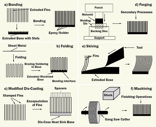
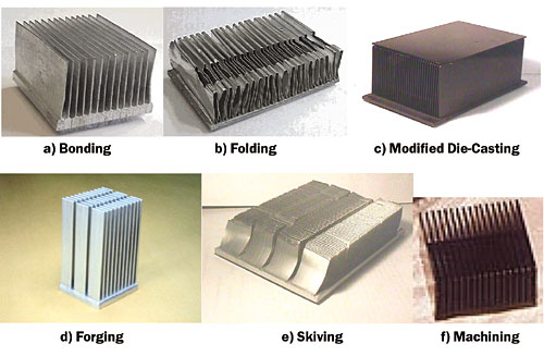
A heat sink thermal optimization, such as the one discussed in a subsequent section, suggests that demanding heat dissipation targets require the manufacture of extremely dense arrays made up of ultra thin fins. While these designs may appear to be out of reach of conventional processes, such as extrusion and die-casting, the challenges can be addressed by the use of modern processes such as those depicted in Figures 1 and 2 [5, 6].
 |
Figure 1. Schematic of advanced heat sink manufacturing processes [5, 6].
 |
Figure 2. Photographs of high performance heat sinks [5, 6].
Bonding
Bonded heat sinks are often built-up extrusions, typically manufactured by assembling extruded plates into slots on an extruded or machined heat sink base, and held in place by an interface, usually a two part thermosetting thermally conductive epoxy or a solder. The bonding agent does however represent a thermal barrier. These heat sinks are often costlier to manufacture, and the base typically requires special machining. Process limitations are usually related to the strength of the bonding agent and dimensional constraints for the slot in the heat sink base. Hybrid heat sinks utilizing different materials for the fins and the base can be accommodated by this process. Bonded fin arrays are most commonly rectangular plate fin arrays.
Folding
Folded heat sinks are built-up sheet metal, manufactured by folding sheet metal into a serpentine fin array. The folded sheets of metal are attached to the base of the heat sink by soldering or brazing, which results in an additional thermal resistance at that interface. However, this contact resistance between the folded fins and the heat sink base is smaller than expected, due to the fact that the “bends” of folded fins are typically flattened while bonding or brazing, thus increasing the contact surface area. Difficulty in achieving smaller fin pitches required to construct dense arrays is a common issue. Similar to the bonding process, this manufacturing method allows flexibility in designing hybrid heat sinks made up of a combination of different materials.
Modified Die-Casting
The modified die-casting process involves the extension of basic die-casting principles, whereby the base of the heat sink is die-cast around a fixtured array of extremely thin stamped fins. The fins are separated by spacers, which prevent the die-cast material from flowing into the fin-to-fin spacing. While it may be possible to manufacture heat sinks of different materials, aluminum is the most commonly used material for this technique. The absence of a so-called interface between the fins and the base eliminates the impact of an interface resistance. This process allows much higher aspect ratios while fulfilling requirements of small inter-fin spacing. These heat sinks are usually combined with a heat pipe to provide a thermal solution.
Forging
In forged heat sinks, the fin arrays are formed by forcing raw material into a molding die by a punch, which usually weighs about 500 tons (453,592.4 Kg). Common problems in forging are the choking of material in the molding die cavity, which could lead to fins of uneven height. Secondary processes may include cutting the fins, machining the base, polishing, or etching. While hot forging is inherently easier, cold forging results in denser and stronger fins. Some of the attractive benefits of forging include high strength, superior surface finish, structural rigidity, close tolerance capabilities, continuity of shape, and high uniformity of material. Aluminum and magnesium alloys are easily forged, and an important economic advantage is a typically low rejection rate for the process. This process category also includes techniques such as impact extrusion and micro-forging.
Skiving
In the skiving process, fins are machined using special tooling, whereby precisely sliced layers from an extruded metal block are bent at the base of the slice to form slender curved fins. Since the fins and base are an integral unit, the interface resistance seen in folded and bonded heat sinks is not present. This process was originally developed to manufacture sparse natural convection arrays, but recent efforts have been focused towards achieving tighter fin spacing, necessary for forced convection cooling. Aluminum 6063 is the preferred material on account of its superior machinability and strength, but copper arrays can also be made. The depth of cut determines the fin thickness and can be very low, resulting in extremely thin fin structures, yielding light and competitive heat sink designs.
Machining
Heat sinks are machined out of a metal block by material removal to create the inter-fin spaces. Most commonly they are manufactured by gang saw cutting on a computer numerical control (CNC) machine. The gang saw consists of multiple saw cutters on an arbor with precise spacing, which depends on the heat sink geometry to be machined. Often, during machining, the fins are damaged and distorted, and require extensive secondary operations. Material is also consumed in an unproductive manner by the generation of scrap metal.
Manufacturing Process Capability
Empirical heat sink manufacturability-related data was obtained from several vendors [6]. This information was then utilized to establish qualitative guidelines for manufacturability, which are presented in Table 1. Some of the data in Table 1 pertains only to arrays of 50 mm fin heights, for which the current analysis was carried out [5, 6]. As detailed in Table 1, modern manufacturing processes, such as bonding, folding, modified die casting, forging, skiving, and machining allow the manufacture of significantly more extreme dimensions compared to traditional methods, i.e., extrusion and die-casting.
Methodology – Thermal Design for Manufacturability of Heat Sinks
The thermal design for manufacturability demonstrated in this section can be summarized in the following steps:
- For a given flow operating point (Pa, m3/s), generate a table of different fin geometries that will satisfy the flow and pressure drop equation for a heat sink. The fin geometry is described by the fin density (fins/cm), the spacing, and the thickness. This table will have a column of fin numbers (say 10-150), and a corresponding column of fin thickness and fin spacing values with each row defining a design which will satisfy the flow operating point. This step can be performed using various models available in the literature [7], and involves solving the pressure drop model.
- For each design generate a thermal resistance versus fin geometry plot or table. Again, one may use any number of models from prior art to do this [7], and, in this case, one would use a thermal heat sink model.
- Use tables similar to Table 1 and those generated via steps 1 and 2 to identify the lowest thermal resistance that can be achieved for each process, and also identify the lowest possible value. The difference between the process constrained design and the minimum thermal resistance design represents the “gap” or potential for improvement. The difference between the achievable values between different processes can then be used to choose a process or determine whether one is willing to change the current process.
 |
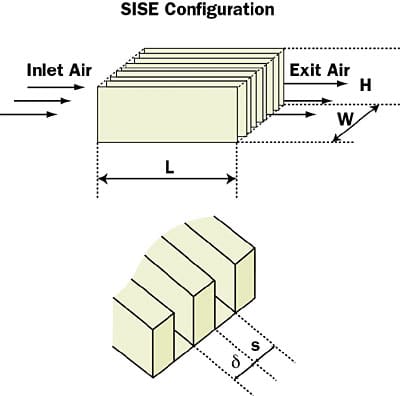
Figure 3. Geometry of the plate fin heat sink analyzed in this article.
Example – Thermal Design for Manufacturability of Heat Sinks
The analytical model developed by Holahan et al. [7] is used in this article for calculating the thermal and pressure drop performance in fully ducted, laminar, parallel plate heat sinks. For the analysis presented in the paper, the base of the heat sink is isothermal and the thickness of the base is assumed to be negligible. The effect of geometric artifacts in the fin structures resulting from the use of different manufacturing processes are also not considered, and all the calculations are based on the rectangular longitudinal fin and channel heat sink design. While there will exist some errors between the use of the model [7] and actual real world performance, it may be expected that within the range of the designs considered, the results can be used to compare designs relative to one another. The simple side-inlet-side-exit (SISE) configuration considered is depicted in Figure 3, showing the nomenclature of the array geometry, including the fin height, H, fin thickness, δ, inter-fin spacing, s, width of base, W, and the length of the heat sink base, L.
 |
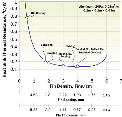
Figure 4. Typical thermal characteristic plot for a heat sink: Thermal Resistance vs Fin Density, 0.1 x 0.1 m, 0.05 m, Aluminum, 20 Pa, 0.01 m3/s.
Figure 4 shows the results of thermal resistance calculations for an aluminum heat sink (0.1 x 0.1 m heat sink base; fin height, 0.05 m), in forced air convection for flow conditions of 20 Pa and 0.01 m3/s. The thermal resistance is defined as the ratio of the excess temperature difference (�C) to the heat dissipation rate (W), where the excess temperature difference is between the bottom surface of the heat sink base and the incoming air at the heat sink inlet. One may assume such a flow condition defined by a pressure drop and flow rate to represent a single point on a fan curve.
For each value of fin density, there is a corresponding fin-to-fin spacing, s, and fin thickness, δ, which meets the pressure drop requirement at the specified flow rate. It should be noted that with increasing fin number both the fin thickness and the spacing decrease. For a given operating condition, described by pressure drop and volumetric flow rate, designs with very small and very large values of the fin density yield high values of thermal resistance, the former due to limited surface area and the latter caused by the highly inefficient thin fins. An intermediate geometry, which minimizes the thermal resistance, can thus be identified. It should be noted that the thermal optimization illustrated in Figure 4 uses a heat sink volume as the driving thermal constraint and not an actual application specification.
For the example illustrated in Figure 4, a minimum value of 0.135�C/W occurs at 4 fins/cm, yielding a design that will dissipate 186 W at a 25�C excess temperature from the base to the inlet air. The fin thickness and spacing for this aluminum device are 0.57 mm and 1.93 mm, respectively with a heat sink mass of 0.308 kg. Returning to Table 1, one can observe that not all the processes are capable of creating a heat sink with such dimensions with a gap aspect ratio of 26 and a fin aspect ratio of 86.
Reflecting on the plot of heat sink thermal resistance versus fin density displayed in Figure 4, the application of the geometrical manufacturing constraints listed in Table 1, as part of the design for manufacturability methodology, can result in sub-optimal thermal performance. It can be seen from Figure 4 and Table 1 that processes which allow creation of thin and densely packed fin arrays, possess a distinct advantage over less advanced techniques. It is thus of paramount importance to understand and identify manufacturing process capabilities and optimize the design within these constraints to achieve cost effective heat sinks.
Summary
The effort discussed herein deals with the development of a ‘design for manufacturability’ methodology for forced convection cooled, plate fin arrays used to form high performance heat sinks for electronic cooling applications. The economic competitiveness of a production technology is the combination of both its process capability and the cost to manufacture. A thermal analysis is utilized in conjunction with process constraints to quantify the performance loss or “gap” between practical and ideal designs, associated with various manufacturing processes. Such a trade-off analysis can than be used to evaluate the suitability of different production techniques for a given air cooling application.
References
- Soule, C., “Future Trends in Heat Sink Design,” ElectronicsCooling, February, 2001.
- Lee, S., “How to Select a Heat Sink,” ElectronicsCooling, June, 1995.
- Pearson, C., The Extrusion of Metals, John Wiley & Sons, Inc., London, 1944,
- Die Casting for Engineers, The New Jersey Zinc Company, N. Y., 1953.
- Iyengar, M., and Bar-Cohen, A., “Design for Manufacturability of SISE Parallel Plate Forced Convection Heat Sinks,” IEEE Transactions on Components and Packaging Technologies, Vol. 24, No. 2, 2001, ISSN 1521-3331, pp. 150-158.
- Iyengar, M., “Resource Constrained Heat Sink Optimization,” Ph.D. Thesis, Department of Mechanical Engineering, University of Minnesota, Minneapolis, March 2003.
- Holahan, M., Kang S., Bar-Cohen, A., “A Flowstream Based Analytical Model for Design of Parallel Plate Heat Sinks,” ASME Proceedings of the 31st National Heat Transfer Conference, HTD-Vol. 329, Volume 7, 1996, pp 63-71.


