Introduction
Silicon became the semiconductor of choice for ICs because of its electrical properties, not because of its mechanical properties. In the earliest days of ICs when chips were small and power levels were low, the mechanical properties of silicon were of little consequence. However, for some time, the opposite situation has been the norm. Now, there are much larger chips, approaching 20 mm on a side and high power levels, exceeding 200W.
We all have heard many times of reliability issues due to the mismatch in the Coefficient of Thermal Expansion (CTE) between a silicon chip and another structure to which it is bonded. There are numerous failure modes in packages, induced by thermal strain. In Part I of this article we will first examine the mechanical properties of silicon and other packaging materials. Then, in Part II (to be published in the November 2007 issue), we will explore the physics of the thermal strain process and evaluate a simple means of calculating warpage in packages due to differential thermal strain.
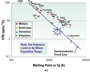
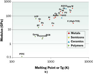
Figure 2. Plots of a) CTE and b) elastic modulus versus melting point for a variety of materials used in packaging. The properties were measured at or near room temperature.
 |
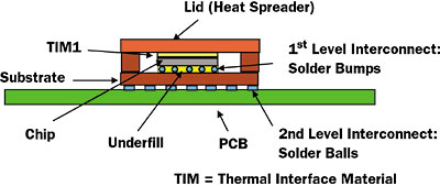
Figure 1. Schematic drawing of a flip-chip package attached to a PCB.
Figure 1 depicts a common configuration for high-power integrated circuits [1]. Structurally, it is a laminate composite assembly. The major package components (IC chip, lid, package substrate, and PCB) are bonded adhesively to their neighbors. The adhesive layers are: TIM1 (between the chip and package lid), C4 solder bumps and underfill (between the chip and the package substrate, and the solder balls (with or without underfill; between the package substrate and the system PCB). Of course, beyond their adhesive function, the solder bump and solder ball layers provide the electrical interconnection between their neighboring components.
During the assembly of the package, it is heated in order to enable the bonding process for each adhesive layer. Examples are the melting and solidification of solder or the curing of an epoxy. As the package cools, the interface will initially be stress free due to the adhesive layer being either in a molten or softened state. However, with additional cooling, the adhesive layer becomes stiffer. Any subsequent differential contraction of the package components will lead to stress within the components and the interfacial layers and some warpage will result. Intuitively, we expect this warpage to depend primarily upon two factors:
- CTE: This represents the fractional change in the length of a component per degree of temperature change when it is not attached to any other component. The change in length of a component, ∆L, due to a change in its temperature is related to the CTE by: ∆L = L x ∆T x CTE. Rearranging terms: CTE = (∆L/L)/∆T = ε/∆T, where ε is the mechanical strain.
- Elastic Modulus: This could be described as the “stiffness” of a material. It is represented by the symbol, M. In a uniaxial stress situation, it equals the ratio of the stress to the strain, or M = σ/ε.
The stress between two bonded components depends on both of these factors. If the CTE difference between two materials is large, but the modulus of one of them is much larger than the other, then the CTE of the stiffer material will dominate. Of course, the relative thickness plays into this, but we will ignore that for the moment.
Material Property Relationships
In the world of solid-state physics, it is understood that the CTE, modulus, and melting point of a material are related to the binding energy between atoms. The higher the binding energy, the more resistant a material is to changes in its length due either to temperature variations or the application of an external stress, and the greater thermal energy it takes to melt it. For polymers, the analog of the melting point is the softening temperature, referred to as the Glass Transition Temperature (Tg). It is natural to expect to see some sort of correlation between the CTE and modulus of a material with its melting point.
Figures 2a and 2b contain log-log plots of the CTE and Modulus for many materials versus their melting point (or Tg for polymers). The material classes represented are metals, semiconductors, ceramics, and polymers. On the whole, the metals, ceramics, and polymers tend to follow the same trend. The exception is the trendline defined by the semiconductors, consisting of Se, Ge, Si, and C. The values of CTE along this trendline lie significantly lower than those of the other material classes. We note that only the high-melting point materials, such as the refractory metals, W and Mo, and the ceramics, AlN and Al2O3, have values of CTE close to Si, although still exceeding it. These metals, unfortunately, are not the best electrical or thermal conductors. The best ones, Cu and Ag, have CTE values ten times higher than that for Si. It is interesting to note that the advanced composite materials combine a form of carbon (diamond or graphite, which have CTE values lower than Si) with higher CTE materials to make a composite whose CTE closely matches that of Si [2].
If a close match for CTE were the only criterion for compatibility with Si, the list of non-composite materials compatible with Si would be very short. However, we have the modulus trump card to play. Figure 2b reveals a consistent trend among the classes of materials of interest, with the modulus increasing with the melting point. The moduli of the materials with the lowest melting points (or Tg) are one or two orders of magnitude lower than Si. These include the polymers and the low-melting point metals, Sn and Pb. In fact, these materials are used in the bonding layers in packages and serve to reduce the mechanical coupling between them. Polymers are also used to make package substrates and PCBs, impregnating glass (SiO2) fiber weaves. The presence of the glass fibers reduces the CTE of the composite but increases the stiffness (and strength) of the board. Please note that in Figure 2a the material, BT (bismaleimide triazine), which is a fiber-reinforced material used in package substrates, lies below the overall trend due to this effect.
These materials and their melting or softening points play important roles in the thermal history of a package and on the stress and strain in the final product. We will explore these effects in detail in Part II of this article in the November 2007 issue.
References
- Guenin, B., “The Many Flavors of BGA Packages,” ElectronicsCooling, Vol 8, No. 1, February 2002.
- Zweben, C., “Revolutionary New Thermal Management Materials,” ElectronicsCooling, Vol. 11, No. 2, May 2005.


