Introduction
More than twenty-five years ago, Tuckerman and Pease first described the use of silicon microchannel cooling for very high power densities [1]. However, the coolers could not be fabricated easily and pressure drops were very high. As chip power densities are now increasing beyond air cooling limits, a variety of liquid cooling methods are being investigated. Due to the high heat transfer coefficient associated with it, microchannel cooling is an attractive approach, but several practical issues need to be addressed. Reviews of microchannel cooling are available [2-4], though only a few recent publications discuss integration of microchannel coolers with packaged silicon chips [5-9]. In previous work [7-9], we addressed some of the practical issues for implementing silicon microchannel cooling in a single chip module (SCM).
Silicon Microchannel Design
Recent progress in high-rate, deep reactive ion etching (DRIE) of Si [10] has greatly simplified the fabrication of silicon microchannel coolers. Also, methods for reducing the pressure drop have been reported including subdividing the flow into multiple heat exchanger zones with shorter channel lengths [11] and manifold designs with large cross-sectional area (i.e. equal, or larger than, the channel cross-sectional area) [12].
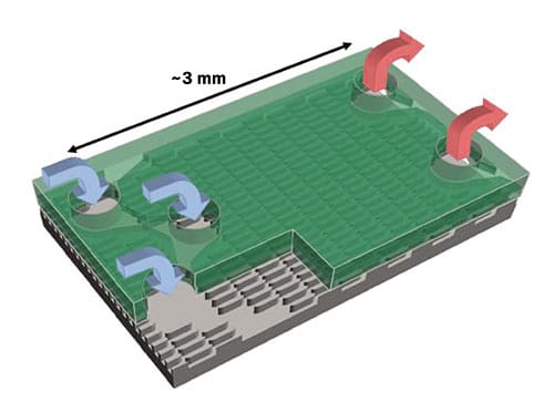
A 3-D rendering of part of an assembled microchannel cooler is shown in Figure 1, where the manifold chip is on top and is shown as semi-transparent green. In operation, alternate zigzagged rows of fluid vias are used as inlets and outlets, so the 20 x 20 mm microchannel cooler is divided into six parallel-fed heat exchanger zones and the flow length between the inlets and outlets is about 3 mm. The fluid vias in the manifold chip were formed as zigzagged arrays of circular openings instead of elongated slots to reduce the likelihood of the manifold wafers breaking during fabrication and assembly. The microchannel coolers had a 0.7 mm seal region around the perimeter, so the actively cooled area was 18.6 x 18.6 mm in size.
 |
Figure 1. 3-D rendering of a portion of an assembled microchannel cooler having six heat exchanger zones.
The manifold chip also contained distribution channels etched about 250 microns deep on the side facing the microchannels to help redistribute the flow to, or from, the fluid vias. Also, the fin segments were removed from the regions under the fluid vias on the channel chip to further aid in the redistribution of the flow at the fluid vias. Staggered fins were used on the channel chip, which allow easy flow redistribution, but appropriate filtration of the coolant is still required. The microchannel coolers were fabricated using photolithography and deep Si DRIE on 150 mm wafers at a MEMs foundry. The manifold and channel wafers were fusion bonded together and then diced to produce the completed Si microchannel coolers. The channel depth was about 250 microns.
Single Chip Module Design
When packaging a chip with a microchannel cooler, there are many constraints which must be considered. The fluid connection should be mechanically decoupled between the cooler and the fluid inlet/outlet manifold to prevent excessive stress on the micro solder balls, which attach the chip to the package substrate. To support a BGA (ball grid array) assembly process of the package to a board, the microchannel cooler and associated manifold were designed to be compatible with a eutectic (~225�C) or Pb-free (~245 -260�C) reflow and with a weight low enough to permit self-alignment during reflow.
Although it has been proposed, given the cost of high-performance processor chips, it is undesirable to form the microchannels directly on the back surface of the chip due to the potential yield loss. Instead, a separate microchannel cooler is bonded to the back of the chip with materials having the lowest thermal resistance possible. If the microchannel cooler is fabricated from silicon, a low thermal resistance, rigid TIM (thermal interface material), such as silver-filled epoxy or thin solder, can be used. If a copper microchannel cooler were used, accommodating the different thermal expansion coefficients of Si and Cu would require a compliant thermal interface material, possibly limiting the overall thermal performance.
 |
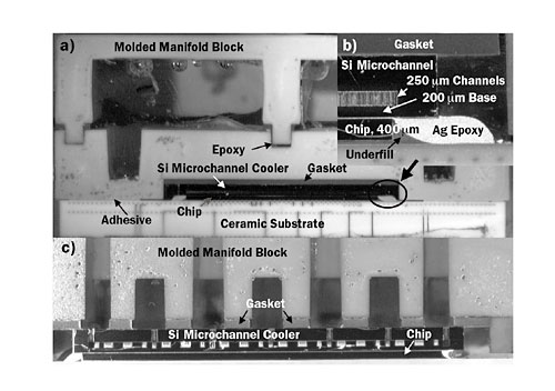
Figure 2. Cross sectional images of complete microchannel SCM.
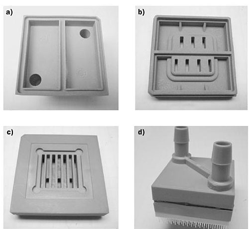
Cross sectional images of an SCM assembly, which meet the above requirements, are shown in Figure 2. The structure, from top to bottom, consists of a two piece manifold block, molded from high temperature plastic, which transforms a single inlet and outlet into alternating inlet and outlet zones. A flexible gasket between the manifold block and the Si microchannel cooler provides mechanical decoupling. In the detailed image of the microchannel cooler (Figure 2b), the microchannels are visible. An 18.5 x 18.6 mm thermal test chip was mounted with micro solder balls onto a ceramic module and underfilled. The microchannel cooler was bonded to the thermal chip using Ag epoxy (white in Figure 2b). The bottom perimeter of the manifold block was bonded to the ceramic package with an adhesive. Details of the manifold block, and a completed SCM, are shown in Figure 3. The underside of the manifold block top part is shown in Figure 3a. Both sides of the manifold block bottom part are shown in Figures 3b and 3c) and a completed SCM appears in Figure 3d. Note that the version of the manifold block shown in Figure 3 is not the same one as shown in Figure 2.
 |
Figure 3. Details of manifold block (a-c) and complete microchannel SCM.
Single Chip Module Results Using Water
Using SCMs as described above, we initially demonstrated cooling 300 W/cm2 [7] with a water flow rate of 1.3 lpm (0.34 gpm) and a pressure drop of 35 kPa (5.1 psi). Based on computer simulations, the area used in calculating the unit thermal resistance was about 5% larger than the powered area of 300 mm2 and about 10% smaller than the full chip area of 342 mm2. The unit resistance between the chip center and the inlet water was 22.1 K-mm2/W.
In subsequent work [8], with a thinned thermal chip, a thin channel chip, Ag epoxy TIM, and a Si microchannel cooler with 20 micron channels on a 50 micron pitch divided into 31 heat exchanger zones, we demonstrated cooling over 400 W/cm2 with a flow rate of 1.0 lpm and a pressure drop of 30 kPa. The average unit resistance between the front of the chip and the inlet was 17.5 K-mm2/W.
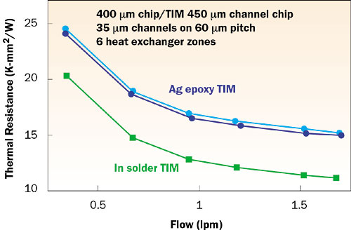
In recent work [9], cooling over 500 W/cm2 was demonstrated in an SCM with 35 micron channels on a 60 micron pitch with 6 heat exchanger zones, a thinned thermal chip, thin channel chip, and an indium solder TIM layer. The average total thermal resistance versus flow rate is plotted in Figure 4 for such an SCM along with two others using an Ag epoxy TIM layer. With indium solder, the total thermal resistance was 12.5 K-mm2/W with a flow rate of 1.1 lpm (0.29 gpm) and a pressure drop of 34.5 kPa (5 psi). Even though a separate cooler was used, these values are close to the 9.0 K-mm2/W unit thermal resistance value reported by Tuckerman and Pease [1] where the silicon substrate below the channels was only 0.1 mm thick and the pressure drop was much higher. Since the exact value of the TIM thermal resistance is not known, the average apparent heat transfer coefficient can only be estimated, and is approximately 200,000 W/m2-K with a flow rate of 1.25 lpm.
 |
Figure 4. Total thermal resistance vs. flow for Ag epoxy and In solder between the microchannel cooler and the chip.
Conclusions
A practical implementation of a single-phase silicon microchannel cooler bonded to a high power chip and cooling over 500 W/cm2 has been demonstrated in a laboratory environment. With a water flow rate of 1.25 lpm, total average unit thermal resistances as low as 12.0 K-mm2/W have been demonstrated for microchannel coolers built from 450 micron thick channel chips attached to 400 micron thick thermal chips using an indium solder TIM. This work has shown that a silicon microchannel cooler can be integrated in an SCM in a simple and practical manner while providing excellent thermal performance at very high power levels.
Acknowledgments
We are deeply indebted to M. Beaumier, B. Furman, N. LaBianca, J. Labonte, J.H. Magerlein, R. Polastre, M. Robert, and R. Schmidt of IBM for their assistance with this work.
References
- Tuckerman, D.B., and Pease, R.F.W., “High Performance Heat Sink for VLSI,” IEEE Electron Dev. Lett., EDL-2, No. 5, 1981, pp. 126-129.
- Phillips, R.J., “Micro-channel Heat Sinks,” in Advances in Thermal Modeling of Electronics, Vol. 2, Bar-Cohen, A. and Kraus, A.D., Eds., ASME Press, New York, 1990, pp. 109-184.
- Sobhan, C.B., and Garimella, S.V., “A Comparative Analysis of Studies on Heat Transfer and Fluid Flow in Microchannels,” Microscale Thermophysical Engineering, 5, 2001, pp. 293-311.
- Kandlikar, S., Garimella, S., Li, D., Colin, S. and King, M., “Heat Transfer and Fluid Flow in Minichannels and Microchannels,” Chap. 3, 2005, Elsevier, pp. 87-136.
- Zhang, H.Y., Pinjala, D., Wong, T.N., and Joshi, Y.K., “Development of Liquid Cooling Techniques for Flip Chip Ball Grid Array Packages with High Heat Flux Dissipations,” IEEE Trans. Compon. Packag. Technol., Vol. 28, No. 1, 2005, pp. 127-135.
- Chang, J-Y., Prasher, R., Chau, D., Myers, A., Dirner, J., Prstic S. and He, D., “Convective Performance of Package Based Single Phase Microchannel Heat Exchanger,” IPACK2005-73126, Proceedings of ASME InterPACK ’05, July 17-22, San Francisco, CA, 2005.
- Colgan, E.G., Furman, B., Gaynes, M., Graham, W., LaBianca, N., Magerlein, J.H., Polastre, R.J., Rothwell, M.B., Bezama, R.J., Choudhary, R., Marston, K., Toy, H., Wakil, J., Zitz, J., and Schmidt, R., “Practical Implementation of Silicon Microchannel Coolers for High Power Chips,” Proceedings of the 21st Annual IEEE Semiconductor Thermal Measurement and Management Symposium, San Jose CA, March 15-17, 2005, pp. 1-7.
- Colgan, E.G., Furman, B., Gaynes, M., LaBianca, N., Magerlein, J.H., Polastre, R.J., Bezama, R.J., Choudhary, R., Marston, K., Toy, H., Wakil, J., and Schmidt, R., “Silicon Microchannel Cooling for High Power Chips,” HVAC&R Research, Vol. 12, No. 4, 2006, pp. 1031-1045.
- Colgan, E.G., Furman, B., Gaynes, M., LaBianca, N., Magerlein, J.H., Polastre, R., Bezama, R., Marston, K., and Schmidt, R. “High Performance and Sub-Ambient Silicon Microchannel Cooling,” in press, Journal of Heat Transfer, August 2007, Vol. 129, Issue 8, pp. 1046-1051.
- Laermer, F. and Urban, A., “Challenges, Developments and Applications of Silicon Deep Reactive Ion Etching,” Microelectron. Eng. (Netherlands) Vol. 67-68, 2003, pp. 349-355.
- Harpole, G.M., and Eninger, J.E., “Micro-channel Heat Exchanger Optimization,” Proceedings of the Seventh IEEE Semi-Therm Symposium, 1991, pp. 59-63.
- Webb, R.L., “Effect of Manifold design on Flow Distribution in Parallel Micro-channels,” paper #35251, Proc. IPACK03, International Electronic Packaging Technology Conference, 2003.


