Introduction
Many liquid cooling solutions in use today employ cooling system devices that result in system pressure drops limited to <0.5 bar (7.25 psi), which allows these systems to fit within the limits of centrifugal pumps. The evolution of alternative cooling devices has brought about pressure drop requirements >1.0 bar (14.50 psi) in some cases [1]. These higher pressure requirements are outside the pressure range of centrifugal pumps due to the prohibitive size of the impeller required.
A different liquid pumping solution must be found that meets these pressure requirements yet adheres to the small package size, low power consumption and high reliability requirements. A properly sized external gear pump can provide pulseless flow at elevated pressures and makes it possible to design a cooling system that is small in size, uses minimal power, and is very reliable.
 |
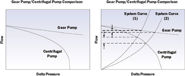
Figure 1. Pump curves and characteristics.
The Pumping Challenges of High Pressure Liquid Cooling
There has been growing interest in the use of cooling technologies such as microchannels and microjet arrays, both of which can be arranged in systems that incorporate multiple cooling elements in series. Such systems are capable of cooling multiple heat sources in a single loop for numerous applications.
Liquid cooling system designs that use multiple cooling elements can provide cooling to the central processing unit (CPU), graphic processing unit (GPU) and other heat sources in a single pass. These technologies also require an increasing amount of pressure to be generated as compared to conventional systems. Gear pumps have the ability to maintain predictable high pressure and flow across many different operating conditions for a variety of cooling systems. The characteristic gear pump curve provides a linear, predictable relationship of pump flow to speed.
In contrast, the pressure generated by a centrifugal pump covers a smaller range of the system curve. Centrifugal pumps can be more difficult to optimize to a given cooling system due to their characteristic non-linear flow curve. Use of a gear pump allows the system designer to provide flow at pressure for several different system designs and simplifies optimization.
Integrated Gear Pump
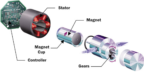
In a typical integrated gear pump, the motor stator fits over the magnet cup and aligns with the driven magnet, which acts as the rotor. The magnet cup forms a fluid pressure barrier, allowing clearance for the magnet to rotate. Rare earth magnet materials are used for maximum motor performance. Stainless steel and plastic pump materials are used to achieve chemical compatibility with a variety of liquids such as potassium formate and propylene glycol.
In operation, the rotating electromagnetic field produced by the stator turns the permanent magnet sealed inside the pump. The speed of the pump is monitored and adjusted with feedback from the controller, which is mounted separately. External control signals (0-5/10 VDC, 4-20 mA) can be used to control pump speed and the flow in the system. With proper circuitry, the control signal can be set proportional to the temperature difference across the cooling device to close the control loop.
This pump can be made to fit a 35 x 35 x 55 mm (.98 x .98 x 2.16 in) size envelope. Flow and pressure can reach 350 ml/min (5.5 gph) and 2 bar (30 psi).
Basic Pump Operation
The gear pump provides flow by first sealing off a gear mesh. As the gears rotate out of mesh and the area between the gear teeth opens up, an expanding volume results, along with a low pressure area. The low pressure area induces the fluid to enter the pump inlet where it is trapped between the gear teeth and cavity wall. The rotation of the gears moves the fluid around the cavity wall into the outlet area and pump discharge, where pressure rises to meet system requirements. Gear pumps are self-priming and can pump liquid without the system being charged at the inlet.
Gear geometry is chosen to deliver the required smooth flow at the design speed, reduce noise and minimize cavitation. Pumping liquids that are more viscous than water also helps keep noise levels to less than 35 dB. The gear flanks transmit torque and seal against each other to prevent fluid leakage. Shaft seals are not necessary. The pumped fluid cools and lubricates the journal bearings.
 |
Figure 2. Integrated gear pump.
The Key to Long Life
Gear pumps are designed to have a long and predictable life, and controlling journal bearing wear is important to limiting the flow loss that occurs over the life of the pump. Gear shaft journal bearings are designed to withstand the gear pressure loads. Shaft size constraints, however, usually result in a situation where full hydrodynamic lubrication is not possible. Journal bearing material choices are therefore made with boundary lubrication in mind. Test results show that ceramic shafts and engineered polymer bushings give wear factors on the order of 1×10⁻¹⁰ mm3/Nm. Depending on operating conditions and the type of fluid used, pump life can reach five years or more.
Reference
- Sauciuc, I., Prasher, R., Chang, J-Y., Erturk, H., Chrysler, G., Chiu, C-P., Mahajan, R.,”Thermal Performance and Key Challenges for Future CPU Cooling Technologies,” Proceedings of IPACK 2005, paper no. 73242.


