Introduction
Most readers of ElectronicsCooling magazine are familiar with the use of fins to increase convective heat transfer area to achieve a lower thermal resistance from a component to the cooling fluid. This Calculation Corner article will address the use of interdigitated fins to provide a mechanically tolerant thermal path between two opposing surfaces (e.g., the back of a chip and the underside of the cap). An example of the structure considered here is shown in Figure 1.
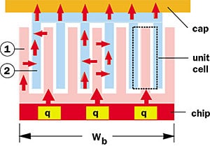 |
Figure 1. Fin-to-fin thermal coupler configuration between chip and cap.
As can be seen in Figure 1, finned heat sink 1 is attached to the top of the chip and a finned heat sink 2 is attached to the inside of the cap. Heat from the chip flows into and along the fins of heat sink 1, across the gaps formed between the interdigitated fins of the two heat sinks, along the fins of heat sink 2 and into the cap. An alternative approach would be to simply conduct the heat through an interfacial media in the gap between the top surface of the chip and the underside of the cap. However, the gap may be too large and the thermal conductivity of the interfacial media too low to achieve a low enough thermal resistance between the two surfaces. In such cases use of the fin-to-fin thermal coupler approach can, in effect, increase the overall surface area of the joint to provide a sufficiently low thermal resistance.
An analogous approach using arrays of fins of circular cross-section was employed to cool multi-chip modules in IBM mainframes for many years [1]. An interdigitated fin geometry similar to that shown in Figure 1 was also used to provide mechanically compliant low resistance thermal paths for chip packages in the Hitachi M-880 mainframe [2].
Thermal Resistance Analysis
The thermal resistance across a fin-to-fin thermal coupler may be determined by first considering the thermal resistance of a single set of interdigitated fins (as shown in the unit cell in Figure 1). The detailed unit cell geometry and properties are shown in detail in Figure 2. The interdigitated fins are of thicknesses t1 and t2 with thermal conductivities k1 and k2 respectively. Both types of fins are of width Wf (i.e., normal to the plane of the paper). The gap between adjacent fins is S and the thermal conductivity of the media in the gap is kg. The engaged length of the fins is Le.
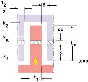 |
Figure 2. Fin-to-fin unit cell details and nomenclature.
The thermal resistance to be determined is that from fin 1 at x = 0 to fin 2 at x = Le. The heat transferred from fin 1 to the left and right halves of fin 2 in Figure 2 may be treated mathematically as heat exchanged between two conductively coupled extended surfaces. Performing an energy balance across the differential element dx in Figure 2 gives rise to the following two differential equations:
 |
where T1 and T2 are the temperatures along the engaged length of fin 1 and fin 2. The parameters m and n are given by
 |
where h is a convective heat transfer coefficient, P is the perimeter of the fin and A1 and A2 are the conduction cross-sectional areas of fins 1 and 2 respectively. Readers familiar with the solution of the one-dimensional fin equation for a fin of uniform cross-section will recognize the similarity between its differential equation and m parameter (e.g., see Incropera [3]) with those given in equations 1 and 2. For the problem under consideration here to be of any utility, the gap, S, must of necessity be small. Therefore, heat transport across the gap will be by thermal conduction. The heat transfer coefficient, h, appearing in equations 1 and 2 is actually an equivalent heat transfer coefficient and is equal to kg/S. Neglecting the thickness of the fins (which is small compared to the width, Wf) the perimeter P is 2�Wf . Substituting for h, P and A in equation 2 results in
 |
To solve the differential equations, the following boundary conditions are applied:
1) dT1/dx = – q/(k1�Wf�t1) at x = 0
2) dT1/dx = 0 at x = Le
3) dT2/dx = 0 at x = 0
4) dT2/dx = – q/(k2�Wf�t2) at x = 0
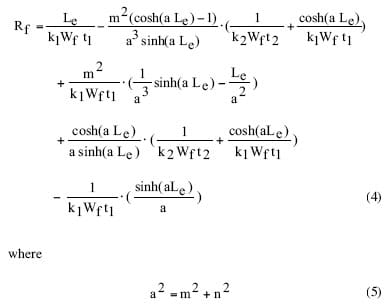
The actual solution, which is beyond the scope of this article, may be obtained using either classical methods or the Laplace transform technique. Once solutions for the temperature profile along each fin have been determined, a formula for coupled fin thermal resistance may be obtained by dividing the difference in the algebraic expressions for T1(x) at x = 0 and T2(x) at x = Le by q (i.e., Rf = Δ T/q). This results in the following expression for the thermal resistance of a single set of interdigitated fins
 |
To determine the overall thermal resistance of a thermal coupler assembly of width Wb it is necessary to determine the number of fins that fit within the given width based upon the fin thicknesses (t1 and t2) and the gap (tg). The number of fin couples (i.e., lower and upper fins), Nwb, is given by
and the overall thermal resistance is
It may be recognized that equation 6 will often result in a non-integer number of fin couples, which of course is not physically realizable. To avoid this it may be more practical to pick an integer value of Nwb a priori and calculate a value of S to use in equation 4. In this case the following expression may be used to determine the value of S
The preceding discussion assumed that the upper and lower fins are of different thicknesses and different thermal conductivities. If the upper and lower fins are of the same thickness, t, and thermal conductivity, k, two different and relatively simpler expressions for thermal resistance have been presented by Hamburgen [4] and Malh�mmar [5]. The expression that Hamburgen [4] presented for thermal resistance of an assembly of coupled fins is
where W = Wb = Wf and
 |
The expression that Malh�mmar [5] presented for thermal resistance of an assembly of coupled fins is
where
It may be noted that even though the expressions (i.e., equations 4 and 7, 9, and 11) are quite different algebraically, they all give the same numerical result for the same conditions.
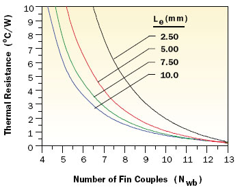 |
Figure 3. Effect of number of fin couples on fin-to-fin thermal resistance.
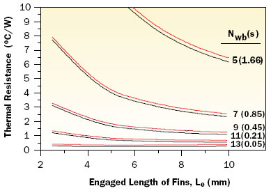 |
Figure 4. Effect of fin engagement length on fin-to-fin thermal resistance.
Example Calculation Results
The following calculation example illustrates the application of the thermal resistance equations for a fin-to-fin thermal coupler assembly. The example assumes a chip with dimensions of 20 x 20 mm. The material for both the lower and upper fin assemblies is assumed to be aluminum with a thermal conductivity of 167 W/m-K and a fin thickness of 1 mm. It is further assumed that the chip and coupler assembly is encapsulated in poly alpha olefin (PAO) oil providing a thermal conductivity of 0.18 W/m-K in the gaps between the fins. Calculations were performed for a range of 5 to 13 fin couples and fin engagement lengths ranging from 2.5 to 10 mm. Figures 3 and 4 respectively illustrate the dependence of fin-to-fin thermal resistance on the number of fin couples and the fin engagement length. The lower (i.e., black) curves in Figure 4 represent the thermal resistance due only to the engaged length of the fins. The upper (i.e., red) curves include the added thermal resistance due to the unengaged lengths (1.27 mm) of both lower and upper fins as well as the lower and upper base thicknesses (1.27 mm). Depending upon the fin count, these additional resistances range between 0.12�C/W for 13 fin couples to 0.28�C/W for five fin couples. The relative effectiveness of coupled fins to reduce the chip to cap thermal resistance can be appreciated by considering the thermal resistance for a fixed gap from chip to cap. For example, the thermal resistance across a 0.18 mm (7 mils) thickness of PAO oil would be 2.5�C/W.
The equations presented in this article provide a useful means of estimating the thermal resistance of a thermal coupler design. Of course the reader should recognize that successful design of a fin-to -fin thermal coupler depends not only on consideration of thermal resistance, but also on other issues, such as mechanical tolerances, manufacturability and ease of assembly.
References
- Chu, R., Hwang, U., and Simons, R., “Conduction Cooling for an LSI Package: A One-Dimensional Approach,” IBM Journal of Research and Development, Vol. 26, No. 1, 1982, pp. 45-54.
- Kobayashi, F., Watanabe, Y., Yamamoto, M., Anzai, A., Takahashi, A., Daikoku, T., and Fujita, T., “Hardware Technology for Hitachi M-880 Processor Group,” Proc. of 41st Elec. Comp. and Tech. Conf. , 1991, pp. 693-703.
- Incropera, F., “Fundamentals of Heat and Mass Transfer,” J. Wiley and Sons, New York, NY, 2006.
- Hamburgen, W., “Interleaved Fin Thermal Connectors for Multichip Modules,” Digital WRL Research Report 91/9, August 1991.
- Malh�mmar, A., “Interleaved Fin Connectors,” http://www.frigprim.com/articels4/Intfin.html.


