Introduction
The thermal resistance of a heat sink is a convenient way of describing its performance but, unlike its electrical counterpart, the thermal resistance of a heat sink is not a constant: it changes significantly with air flow. How we “understand” heat sinks is revealed by the models we use to describe their thermal resistance. Most thermal engineers use a single-term convective resistance model: Rth=1/hAeff. This is a legacy from the days of simple, low-density, finned heat sinks. It is simple but it does not accurately describe the thermal resistance of high fin-density heat sinks. This article has two parts. The first part summarizes three current approaches to predicting thermal resistance and compares them for accuracy: (1) the ‘legacy’ single-term convective resistance model, (2) a two-term thermal resistance model, and (3) heat exchanger theory. The second part provides some examples of the operational advantage of thinking about heat sinks as heat exchangers.
The Convective Resistance Model
Under this model, the thermal resistance of the heat sink is treated as a single convective resistance and the base temperature is assumed uniform (perfectly effective heat-spreading). Fin efficiency, ηfin, or overall surface efficiency, ηo , may be used to account for the temperature distribution in the fins and allow the effective area of the fins to be added to the ‘prime area'(the base area exposed to the flow) to compute the total effective area:
 |
Often, the heat transfer coefficient is taken as the fully developed, laminar flow value for constant wall temperature. This value is independent of flow rate leading to the expectation that the thermal resistance of a heat sink should be independent of the flow through it. This is clearly not true.
A more sophisticated model was proposed using “h” as “an appropriate average over the passage length” to account for entrance effects. Teerstra, Yovanovich, and Culham (1999) [1] developed a continuous predictor for the average value of h as a function of passage length, assuming laminar heat transfer. Simons (2003) [2] used this approach in a convective resistance model and Haskell (2006) [3] showed that the model is still useful. This model accounts for the velocity dependence of the entrance effects, but does not account for the energy balance effects.
Using any ‘convective resistance’ model is equivalent to assuming that the air remains at inlet temperature as it passes through the heat sink. This was reasonable when the heat sinks were not very effective, but it is certainly no longer reasonable.
The Two-Resistance Model: Convective Resistance Plus Fluid Resistance
Azar and Tavassoli (2003) [4] proposed adding a ‘fluid resistance’ term to the convective resistance to get the ‘total resistance.’
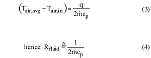
Simons (2006) [5] described this as a “�.caloric, or apparent fluid resistance, Rfluid” and showed its derivation in terms of the change in air temperature within the heat sink:
 |
Simon’s final prediction of the heat transfer rate, adjusted for the difference in notation, was the same as heat exchanger theory would yield (except for an unfortunate typographical omission of the minus sign on one term).
 |
The two-resistance model gets the right answer but there are thermodynamic rules that must be obeyed in developing thermal analogs like resistance and capacitance and calling 1/(2![]() cp) a ‘resistance’ violates those rules (See the appendix for a discussion of the rules).
cp) a ‘resistance’ violates those rules (See the appendix for a discussion of the rules).
The Heat Exchanger Model
Heat exchanger theory was developed to deal with two-fluid systems: a hot fluid transferring heat to a cold fluid. The nomenclature reflects this history. The three most important terms used in applying heat exchanger theory to heat sinks and cold plates are: Effectiveness (ξ), Capacity Rate (![]() cp), and NTU (hAeff/
cp), and NTU (hAeff/![]() cp). The term NTU is sometimes referred to as the “dimensionless size” of the heat exchanger: the ratio of the convective conductance to the flow capacity.
cp). The term NTU is sometimes referred to as the “dimensionless size” of the heat exchanger: the ratio of the convective conductance to the flow capacity.
The effectiveness of a heat exchanger is defined as “the ratio of the actual heat transfer rate to the maximum heat transfer rate that could be transferred for the same initial states and flow rates.”
Applying this definition to a heat sink, the actual heat transfer rate is:
The maximum possible heat transfer rate would be:
For a heat sink, the effectiveness equation is:
The actual heat transfer rate can then be written as:
For the general heat exchanger case, the effectiveness is a function of three parameters: flow arrangement, Cmin/Cmax, and NTU. For the special case of uniform metal temperature, the effectiveness is independent of flow arrangement and the system behaves like a two-fluid situation with Cmin/Cmax=0. Only one parameter remains, NTU, and the effectiveness is given by:
The actual heat transfer rate is then:
And the thermal resistance is:
 |
Equation (12) shows the complex way in which the flow affects heat sink performance.
One should not underestimate the value of a simple result like ξ=1-exp (-NTU). Although it exactly describes the performance of only one simple system, it is a good model for many systems where the walls are NEARLY uniform in temperature. Using this simple model, you can make good decisions and, when you need better numbers, you can get them from your CFD code.
There is nothing new in the idea of using heat exchanger theory in electronics cooling. Simons (2005) [6] used a two-fluid heat exchanger model to estimate the temperature in a sealed enclosure cooled by a heat exchanger that served as one wall of the enclosure. Marthinuss and Hall (2004) [7] presented a good summary of compact heat exchanger theory, including sample data from Kays and London (1964) [8] and discussed the advantages of the approach. Copeland (2005) [9] presented a very compact discussion of a water-cooled heat sink, in heat exchanger terms, and showed how the analysis easily accommodated novel micro-structures. Nakayama (2006) [10] began his analysis of a finned heat sink system by saying: “The conductance of the finned heat sink can be written in a concise form using the heat exchange effectiveness (ξ), the mass flow rate of air in the inter-fin passages (![]() [kg/s]) and the specific heat of air (cp[J/kgK]).” The present author has reviewed this subject previously [11] and Webb (2007) [12] has also stressed the importance of using heat exchanger theory instead of simpler approximations.
[kg/s]) and the specific heat of air (cp[J/kgK]).” The present author has reviewed this subject previously [11] and Webb (2007) [12] has also stressed the importance of using heat exchanger theory instead of simpler approximations.
Comparing the Models
The convective resistance model of thermal resistance is:
Using this to calculate the heat transfer rate yields:
Using heat exchanger theory with Cmin/Cmax=0 yields the following:
 |
We can compare (15) and (16) at different flow rates using the first few terms of a series representation for ex:
 |
As the flow changes, the NTU changes but the thermal resistance does not. The two models thus produce very different results as the heat sinks become more effective, as summarized in Table 1.
Table 1. Comparing the ‘Convective Resistance Only’ Model with the
‘Heat Exchanger Effectiveness’ Model as Air Flow Changes
|
Between 25% and 90% effectiveness, where modern high density heat sinks are designed, the convective resistance model greatly over-predicts the heat transfer.
Further Advantages of the “Think Heat Exchanger” Approach
Extrusion and bypass are two of the nuisances that arise with heat sinks. Both are related to the heat sink’s response to changes in air flow. The heat exchanger model gives us a way to approach these situations.
The Effect of Extrusion
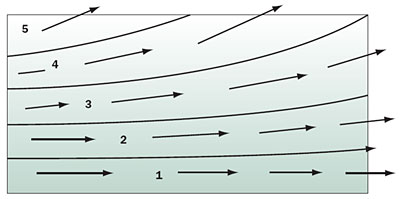
When air that has entered the front face of a heat sink is ejected from the top surface of the heat sink, that is called extrusion. It arises from a mismatch in the internal and external pressure gradients. The axial pressure gradient required to sustain flow inside a heat sink is determined by the passage geometry and the flow rate. If the external pressure gradient is not high enough, the flow decelerates. The stream-tubes spread until enough flow is extruded out the top of the heat sink to satisfy the momentum equation. Figure 1 represents the flow distribution between the fins of a parallel plate fin heat sink under those conditions. This ‘cartoon’ was drawn from flow visualization observations at Stanford.
 |
Figure 1. Flow extruding from the top surface of an unshrouded heat sink passage.
The associated heat transfer problem is to calculate how much heat is transferred to the air while it is in the heat sink. Figure 1 shows five stream tubes, each carrying one fifth of the total flow. These act as five separate heat exchangers, in parallel. Each has the same capacity rate, but they have different heat transfer areas (dictated by the shape of the stream tubes), and (to some extent) different average heat transfer coefficients. For the ith stream tube:
The total heat transfer is simply the sum of five terms.
Predicting the Effect of Bypass
Flow takes the path of least resistance. If the path through the heat sink requires a higher pressure drop than the path around it, the approaching flow will divide with some going over, under, or around the heat sink: this is called bypass. Lee et al. (1990) [13] reports that bypass can reduce thermal performance “�more than 20%.” Wirtz and Chen (1993, 1994) [14, 15] report that the performance degradation due to bypassing can reach 50%. Butterbaugh and Kang (1995) [16] showed that the thermal performance of a heat sink correlated with the pressure drop across it, rather than with the approach velocity.
Bypass always reduces the heat transferred by a heat sink. Convection resistance models cannot explain this effect. Even the “appropriate average h” model advanced by Teerstra et al. [loc. cit.] does not explain the magnitude of the effect, as demonstrated by Simons (2004) [17], although it does show some of the effect.
Bypass can arise from simple, inadvertent changes in a system. For example, reducing the physical size of an adjacent component reduces the local pressure gradient and will cause an increase in the thermal resistance of the heat sink. Similarly, opening up board spacing will also increase the heat sink’s thermal resistance. Note that these “heat sink problems” might be solved by simply putting some blockage back into the system.
Conclusions
The heat exchanger model deserves to be accepted as the default model of describing heat transfer performance of heat sinks. It accurately describes the effect of flow rate on heat sink performance and it offers insight into several problems afflicting heat sink applications.
Another advantage to using heat exchanger terminology is that it will keep the electronics cooling literature consistent with the rest of the heat transfer community.
Appendix
Analog Modeling of System Behavior
Electrical analog circuits can be used to study the behavior of fluid mechanical, thermal, or mechanical systems, but only if the analog elements obey the definitions of electrical resistance, capacitance, or inductance. If the elements are not properly described, the model will predict “unrealistic” behavior.
Analog elements must be based on the rate equations that describe the flow of a conserved property (one that is neither created not destroyed within the component) in response to a potential drop that causes that flow. The physical laws of fluid mechanics, heat transfer, and mechanics identify the potentials and flows.
Figure A1 shows a generic “pure component” (only one attribute) along with its associated flows and potentials. The identity of the component (R, L, or C) can be learned from the relationships between the F’s and P’s.
The rules for this identification are:
- For any component, the flow is conserved and the potential must decrease in the direction of the flow.
- If the potential drop (P1-P2) is linearly proportional to the flow, F, i.e., if (P1-P2) = R�F
then the component is a resistor of resistance R.
- If the potential drop (P1-P2) is linearly proportional to the time-integral of the Flow, i.e., if
then the component is a capacitor of capacitance C.
- If the potential drop (P1-P2) is linearly proportional to the derivative of the Flow, i.e., if
then this component is an inductor of inductance L.
Note: There is no inductive counterpart in thermal modeling. Inductance is found only in systems that have the inertial property.
 |
Figure A1. A generic component with potentials and flows indicated.
We can summarize these relationships as:
 |
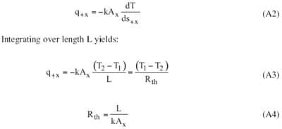
A steady-state, one-dimensional conduction situation provides a simple example for thermal modeling. The basic rate equation is Fourier’s Law: The rate of heat transfer by conduction in the +x direction equals (-kAx) times the derivative of temperature with respect to distance in the +x direction and Ax is the area perpendicular to the x-direction.
 |
Fourier’s Law, Equation A2, establishes that temperature is the potential that forces the flow of heat by conduction. Equation A3 establishes the fact that the potential difference is linearly related to the flow (and not to the derivative or integral of the flow) and, therefore, the element is a “resistor.” The potential, T, diminishes in the direction of heat flow (i.e., T2<T1).
Why Does  Not Qualify as a Proper Analog Resistor?
This question can be addressed by considering Equation A5 which describes the process from two aspects: the rate process at the walls (convective heat transfer) and the energy balance on the air. The term (Tbase-Tair,in) is clearly the potential that drives the convective heat transfer rate and the convective resistance can be taken to be 1/hA. On the other hand, the term (Tair,out-Tair,in) is not a potential in any recognized rate equation; it is simply the consequence of an energy balance on the fluid. Since we have no engineering rate equation that uses that as a potential, we cannot use it as the basis for a model element.
Also, from physical reasoning, the temperature is increasing in the direction of mass flow, not decreasing.
The process described by the rise in temperature of the air is not, itself, a heat transfer process � it is simply a mass-associated transport of thermal energy. There is no “Flow” of heat driven by a gradient of a “Potential.”
What’s Wrong with Using It Anyway?
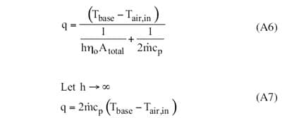
If the above discussion is not convincing enough, then consider Equations A6 and A7. They show that using as a ‘fluid resistance’ gives the wrong result in a limiting case; it fails the simplest test of usefulness.
 |
References
- Teerstra, P., Yovanovich, M., and Culham, J., “Analytical Forced Convection Modeling of Plate-Fin Heat Sinks,” Proceedings of 15th IEEE Semi-Therm Symposium, 1999, pp. 34-41.
- Simons, R., “Estimating Parallel Plate-Fin Heat Sink Thermal Resistance,” ElectronicsCooling, Vol. 9, No. 1, February 2003.
- Haskell, M., “Thermal Resistance Comparison of Graphite Foam, Aluminum, and Copper Heat Sinks,” ElectronicsCooling, Vol. 12, No. 1, February 2006.
- Azar, K. and Tavassoli, B., “How Much Heat Can Be Extracted from a Heat Sink?” ElectronicsCooling,Vol. 9, No. 2, May 2003.
- Simons, R., “A Simple Thermal Resistance Model – Isoflux versus Isothermal,” ElectronicsCooling, Vol. 12, No. 1, February 2006.
- Simons, R., “Estimating Temperatures in an Air-Cooled Closed Box Electronics Enclosure,” ElectronicsCooling, Vol. 11, No. 1, February 2005.
- Marthinuss, J. and Hall, G., “Air Cooled Compact Heat Exchanger Design for Electronics Cooling” ElectronicsCooling, Vol. 10, No. 1, February 2004.
- Kays, W., and London, A., “Compact Heat Exchangers, 2nd Ed.,” McGraw Hill Book Co., New York, 1964.
- Copeland, D., “Review of Low Profile Cold Plate Technology for High Density Servers” ElectronicsCooling, Vol. 11, No. 2, May 2005.
- Nakayama, W., “Exploring the Limits of Air Cooling,” ElectronicsCooling, Vol. 12, No. 3, August 2006.
- Moffat, R., “Modeling Air-Cooled Heat Sinks as Heat Exchangers,” Proc. of the 23rd IEEE Semi-Therm Conference, March 20-22, 2007.
- Webb, R., “Heat Exchanger Design Methodology for Electronic Heat Sinks,” Transactions of the ASME, Journal of Heat Transfer; July 2007, No l. 129, No. 7, pp. 899-901.
- Lee, R., Huang, H., and Chen, W., “Thermal Characteristic Study of Extruded-Type Heat Sinks in Considering Air Flow Bypass Phenomenon,” Proc. IEEE Semiconductor Thermal and Temperature Measurement Symposium, 1990, pp. 95-102.
- Wirtz, R., and Chen, W., “Longitudinal Fin Heat Sink Performance in Arrays of Low-Profile Electronic Packages,” Proceedings of the ASME International Electronics Packaging Conference, Sept. 29 – Oct 2, 1993.
- Wirtz, R., Chen, W., and Zhou, R., “Effects of Flow Bypass on the Performance of Longitudinal Fin Heat Sinks,” ASME Journal of Electronics Packaging, Vol. 116, No. 3, Sept. 1994, pp 206-211.
- Butterbaugh, M., and Kang, M., “Effect of Airflow Bypass on the Performance of Heat Sinks in Electronic Cooling,” ASME EEP, vol. 10-2, 1995, pp 843-848.
- Simons, R. E. “Estimating the Effects of Flow Bypass on Parallel Plate-Fin Heat Sink Performance”. ElectronicsCooling. February, 2004.


