Introduction
A thermoelectric cooler (TEC) is a solid-state refrigerator that operates on the Peltier effect. The absence of moving parts, compact size, precise temperature control ability and reliability all combine to make the TEC a unique refrigerator. TECs find application [1, 2] in many fields from simple food and beverage coolers for an afternoon picnic to extremely sophisticated temperature control systems in space vehicles. More and more TECs are being used to solve severe cooling problems, especially in the electronics industry; for example, the cooling of laser diodes [3].
Due to high demand and economic values, many manufacturers are marketing a wide variety of TECs [4]. Every manufacturer specifies their TECs using performance curves and several limit values: ΔTmax, Imax, Vmax and Qmax [5]. Thermal management engineers need to find the highest performance TEC, optimize the operating parameters using simple calculations, and simulate the overall cooling system (including the TEC) using commercially available CFD software. To do all this it is necessary to know the basic physical properties (s, ρ and k) of the TEC materials. Unfortunately, most manufacturers do not provide this kind of information in their product catalog. Therefore, thermal designers usually find it difficult to obtain these physical properties. Huang et al. [6] designed an experiment which can accurately measure the physical properties of a TEC module. The problem is that most thermal designers usually do not have either accessibility to the necessary apparatus or sufficient time to make the required measurements.
This article presents a simple method to calculate the physical characteristics of a TEC module (i.e., device Seebeck voltage SM, device electrical resistance RM and device thermal conductance KM) based upon the information ( ΔTmax, Imax, Vmax and Qmax) readily available in the vendor datasheet. The fundamental physical properties s, ρ and k can then be calculated if N (number of couples) and G (ratio of the cross-sectional area/length of each thermoelectric element) are known. Further, this article presents an application example to evaluate and optimize the operating parameters of TEC by simple calculations.
Modeling
Basic Model for TEC
The following theoretical equations (1-4) for a TEC are provided in many handbooks and papers [7-10]:
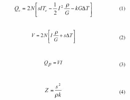 |
To simplify, define SM, RM and KM by equation (5-7):
SM = 2sN (5)
RM = 2ρN/G (6)
KM = 2NkG (7)
Then, equations (1, 2 and 4) can be expressed as equations (8-10):
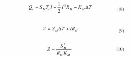 |
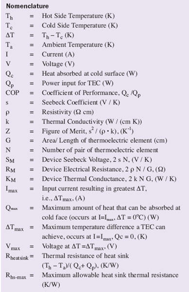
The parameters s, ρ and k are fundamental physical properties of the TEC materials and SM, RM and KM are the physical characteristics of the TEC as a device. The figure-of-merit, Z, is directly related with the ability of a TEC to pump heat and is a criterion to evaluate the quality of the TEC [11]. All these parameters are necessary constants in calculations or simulations using the above equations. Unfortunately, none of these are generally listed in the manufacturer’s catalogue. What the manufacturers usually list are ΔTmax, Imax, Vmax, and Qmax at a specified hot side temperature Th.
Expressions for ΔTmax, Vmax, Imax and Qmax
Inspection of equation (8), reveals that DT varies as the square of current I when Qc is zero, as shown by equation (11).
 |
Differentiating equation (11) with respect to I leads to equation (12):
 |
Setting equation (12) equal to zero and solving for I to maximize ΔT leads to equation (13):
 |
Equation (13) is the prerequisite to produce the maximum temperature difference ΔTmax, and the current is defined as the maximum current Imax. The voltage at this time is defined as the maximum voltage Vmax. Now, inserting the value of Imax from equation (13) into equation (11) results in equation (14) for ΔTmax:
 |
Replacing ΔT and I with ΔTmax and Imax in equation (9), an expression for Vmax can be obtained, as shown by equation (15).
Usually performance specifications for a TEC lists ΔTmax, Imax , Vmax at a specific hot side temperature Th. Replacing Tc with (Th– ΔTmax) in equations (13) and (14), equations (16) and equation (17) are obtained.
 |
In addition, Qmax occurs also at a specific hot side temperature when I = Imax and ΔT = 0�C. Therefore equation (8) can be reformed as equation (18):
Method I to Calculate SM, KM and RM
Although the three TEC physical characteristics parameters SM, RM and KM are unknown, as noted earlier, vendor datasheets usually give the four maximum parameters ΔTmax, Vmax, Imax and Qmax, and in addition there are four equations (15-18). Any three of the four equations can be used to solve and get expressions for SM, RM and KM. Method I in this article uses only three equations ΔTmax, Vmax and Imax, and leaves the fourth for Qmax alone. In this way, equations (19-22) are obtained from equations (10), (15-17) to determine Z, SM, KM , and RM:
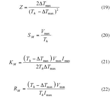 |
As long as SM, RM and KM are known, s, ρ and k can be calculated according to equations 5-7, if N and G are known.
Method II to Calculate SM, KM and RM
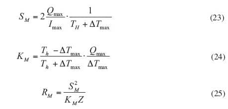
As indicated above, any three of the four equations (15-18) can be used to solve and get the expression for SM, RM and KM. Method II in this article can be used to calculate SM, RM and KM according to the three equations for ΔTmax, Imax and Qmax, without using Vmax. According to method II, the resulting formulations are equation (19) and equations (23-25).
 |
Ideally, there should be internal consistency between the four equations (15-18), and the calculation results of the two methods should be the same. However, this is not always the case. Errors do exist, which can be seen in the following application example.
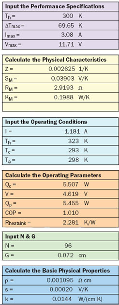
Table 1. Spreadsheet Calculator for TEC
 |
Application and Discussions
Using the preceding formulas, a spreadsheet calculator can be made to determine the physical characteristics, basic physical properties and operating parameters of TECs as shown by Table 1. After inputting the performance specifications in terms of Th, ΔTmax, Imax and Vmax, the physical characteristics SM, RM, KM and Z are calculated according to equations 19-22 in method I. Then, inputting the operating conditions I, Th, Tc, and Ta, operating parameters Qc, V, Qp, COP and Rheatsink are calculated according to equations 1-3, 26 and 27.
 |
In addition, if values for N and G for the TEC under consideration are provided as input, the fundamental physical properties s, ρ and k can also be calculated.
Application Example
For an application example, a commercially available TEC is to be selected to cool a laser diode, which dissipates 5.5W and must be kept at 20�C for an ambient temperature of 25�C. It is also necessary to keep the heat sink as small as possible; in other words, the heat sink thermal resistance Rheatsink should be close to the maximum allowable heat sink thermal resistance Rhs-max.
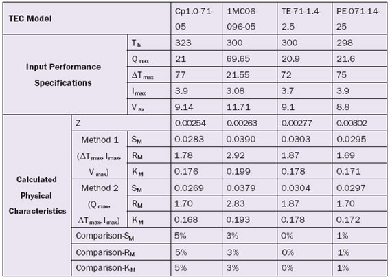
1) TEC Selection – As is known, Z is a criterion of a TEC’s ability to pump heat. Therefore, the Z value of different TECs from different manufacturers is calculated according to the information from the manufacturers’ catalogues. As shown in Table 2, the value of Z for the second TEC (1MC06-096-05) is in the middle. Considering other factors such as its smallest size, TEC 1MC06-096-05 is selected.
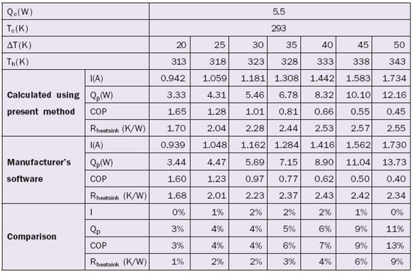
2) Determining Operating Parameters – The operating parameters for TEC 1MC06-096-05 are calculated for different DTs using the spreadsheet calculator (Table 1). The performance specifications (Th, ΔTmax, Imax and Vmax) shown in Table 2 for the selected TEC (1MC06-096-05) are entered along with the operating conditions (I, Th, Tc, and Ta). The current, I, entered in the calculator is then adjusted until the calculated value of Qc equals the specified heat load (i.e., 5.5W). The result of the calculations for each Δ T are recorded as shown in Table 3. As also shown in Table 3 for the example calculation, the value of allowable heat sink thermal resistance, Rheatsink, reaches its maximum value of about 2.57�C /W at a ΔT = 45�C. However, the bigger value of COP of 1.01 occurs at ΔT = 30�C, so this chosen as the design temperature difference.
Table 2. TECs from Different Manufacturers
 |
Discussion about the Two Methods to Calculate SM, KM and RM
Two methods to calculate SM, RM and KM have been discussed in this article. Errors exist between the two calculation methods, and the biggest is 5%, as shown by Table 2. One reason is that our model, representing TEC operation, equations (8) and (9), is an ideal one and the TEC module parameters (SM, RM and KM) are taken as constants. Actually, SM, RM and KM depend on the temperature, more or less. Another reason is that the performance specifications from manufacturers are experimental results. Usually different manufacturers use different experimental methods under different conditions.
Table 3. Operating Parameters of TEC (1MC06-096-05)
 |
Comparison with Manufacturer’s Software
In Table 3, calculated example results are compared with results from the manufacturer’s software. As may be seen some discrepancies do exist and the further Th is from 300K (which is the hot side temperature at which performance specifications are given), the bigger the discrepancy for Qp. This is because Z, SM, RM and KM are not always constants as stated before. Actually, Z, SM, RM and KM are dependent on the temperature to some degree. Notwithstanding this discrepancy, a difference below 10% is acceptable.
Surely, the manufacturer’s software would be expected to be more accurate. However, not every manufacturer provides software. Although performance curves can sometimes be used in place of calculations, most often performance curves are given at a specific Th, for example, 25�C or 50�C, which is usually different from in the application under consideration. Another problem is that reading off curves and performing the required iterations is tedious and troublesome, especially when many different ΔTs must be considered. Accordingly, the calculation method presented in this article may be quite useful due to its simplicity and convenience, especially for the initial estimates during the cooling design process.
Summary
A simple method to calculate the physical characteristics of a TEC and evaluate the performance of the TEC has been presented in this article. The comparison and discussion shows that some imperfections exist for the calculation method. Notwithstanding this, the calculation method is useful due to its simplicity and convenience, especially as an aid in the selection of a TEC and to obtain initial estimates of its performance in the desired application.
Acknowledgement
The author wishes to thank the editor Robert Simons for his efforts in improving readability. The author also wishes to thank the reviewers for their constructive comments of an earlier version of this article.
References
- Simons, R. and Chu, R., “Application of Thermoelectric Cooling to Electronic Equipment: A Review and Analysis,” 16th IEEE SEMI-THERM symposium, pp.1-9, 2000.
- Riffat, S., Ma, X., “Thermoelectrics: A Review of Present and Potential Application,” Applied Thermal Engineering, Vol. 23, pp. 913-935, 2003.
- Lee, H., Yoon, J., Kim, C-J, “Numerical Analysis on the Cooling of Laser Diode Package With a Thermoelectric Cooler,” Heat Transfer- Asian Research, Vol. 30, Issue No. 5, pp. 357-370, 2001.
- http://www.peltier-info.com/manufacturers.html
- http://www.melcor.com/
- Huang, B., Chin, C. and Duang, C., “A Design Method of Thermoelectric Cooler,” International Journal of Refrigeration, Vol. 23, pp. 208-218, 2000.
- Chein, R. and Huang, G., “Thermoelectric Cooler Application in Electronic Cooling,” Applied Thermal Engineering, Vol. 24, pp. 207-2217, 2004
- Rowe, D., “CRC Handbook of Thermoelectrics,” CRC press, Inc., 1995.
- Gierscheck, J. and Johnson, D., “Latest Developments in Thermoelectrically Enhanced Heat Sinks,” ElectronicsCooling, Vol. 11, No. 3, August 2005.
- Simons, R., “Application of Thermoelectric Coolers for Module Cooling Enhancement,” ElectronicsCooling, Vol. 6, No. 2, May 2000.
- Simons, R., “Effect of Improved Thermoelectric ZTs on Electronic Module Coolability,” ElectronicsCooling, Vol. 12, No. 4, November 2006.

