Introduction
Existing technologies typically utilize air to carry the heat away from a heat sink that is thermally coupled to the microprocessor. Higher performance devices such as workstations, “gaming” PCs, or tower servers that utilize components with greater power dissipation can require more aggressive cooling technology. A high-performance alternative to heat sinks is a liquid-air hybrid system, comprising a microchannel cold plate attached to the chip, a liquid-to-air heat exchanger, a pump to circulate single-phase liquid coolant through the microchannel cold plate and the heat exchanger, and a fan or blower that forces ambient air through the air-side of the heat exchanger.
Microchannel structures have been shown to exhibit significant heat transfer rates from extremely small volumes [1, 2]. However, their successful integration into commercially viable miniature liquid-to-air hybrid cooling systems will likely be determined by system-level factors such as manufacturability, reliability, weight, volume, material compatibility, energy efficiency, and, ultimately, cost. While previous studies have focused on optimizing the microchannel cold plate device or the heat exchanger design, the present study focuses on the thermal optimization and design for manufacturability of the entire cooling system. Optimal system design with and without manufacturability constraints is presented to quantify the “gap” between ideal and practical solutions. Furthermore, the inclusion of a specific representative commercial pump and fan characteristics leads to a practical system-level analysis.
Modeling
A thermal resistance-based network model is constructed to characterize the system physics. Heat transfer and flow parameters on the liquid and air sides, as well as spreading in the microchannel heat sink base, are predicted using correlations from the literature. Heat extraction optimization is linked to heat rejection capability using established heat exchanger relations.
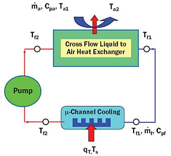 |
Figure 1. Schematic representation of a hybrid liquid�air cooling system.
The System Model
Figure 1 shows a schematic of the entire system, for which the thermal resistance, Rsystem, between the cold plate base and the inlet ambient air, can be defined by adapting the model from Simons [3] as
 |
In these equations, Rhs and Rhr are the thermal resistances to heat removal (microchannel) and to heat rejection (liquid-to-air heat exchanger), respectively, and f, and Cpf, are the mass flow rate and specific heat of the liquid side. The liquid side caloric resistance (1/
fCpf) is subtracted from the sum of the heat removal and heat rejection components because the liquid accepts and then rejects the heat, and thus does not experience a net temperature rise during operation. Temperatures Ts, Ta1, Tf1, and Tf2 are those of the heat source (maximum), inlet ambient air, inlet coolant fluid, and exit coolant fluid, respectively, while qT is the total heat dissipation of the system. The nomenclature discussed above is shown in Figure 1.
Summary of Component Models
The maximum thermal resistance of a microchannel cold plate is calculated by constructing a resistance network made of several parts: the heat sink base bulk conduction, the heat sink base spreading conduction, the base and fin area convection, and the coolant caloric components. The hydraulic resistance to coolant flow through the microchannel cold plate is represented by the total pressure drop that is the sum of the parts, namely, the inlet manifold loss, the contraction loss, the frictional losses in the channels, the expansion loss, and the exit manifold loss. Laminar flow is assumed.
The heat exchanger is modeled as a compact plate and fin type cross flow device using the ε-NTU method and by assuming the two fluid streams to be unmixed. The total thermal conductance of the heat exchanger is the sum of the liquid-side, the air-side, and the wall conduction components. Laminar flow is assumed in the heat exchanger for both the liquid and air loops, and longitudinal heat conduction effects are factored in. The air side heat exchanger pressure drop is calculated as the sum of the entrance contraction loss, the channel (fin core) loss, and the exit expansion loss. A detailed description of these models and the correlations employed can be found in Iyengar and Garimella [4].
Methodology
The thermal optimization and design for manufacturability demonstrated in this section can be summarized in the following steps [4, 5]:
- i. Discretize the pump and fan curves into individual flow operating points that span the device capabilities. Each operating point is represented by a pair of values, i.e., a pressure (Pa) and a volumetric flow rate (m3/s).
ii. For each flow operating point (Pa, m3/s), generate a table of different fin geometries that will satisfy the flow and pressure drop equations for the cooling structure, i.e., microchannel cold plate or the air-side heat exchanger core. The fin geometry is described by the fin density (fins/mm), the fin spacing, and the fin thickness. So, this table will have a column of fin numbers (say 10-200), and a corresponding column of fin thickness and fin spacing values, with each row defining a different design which will satisfy the flow operating point. This step can be performed using various models available in the literature [4], and involves solving the pressure drop model for the relevant cooling structure.
iii. For each operating point, generate a thermal performance metric versus fin geometry plot or table. For the microchannel cold plate, this metric can be the thermal resistance, and for the heat exchanger core, it could be the thermal conductance. A different metric is used for the microchannels and heat exchangers, respectively, based on the preferred design related usage in practice. Again, models from the literature may be used for these calculations [4].
iv. Use the tables generated via steps (i) and (ii) to identify the best thermal performance metric that can be achieved for a set of manufacturing constraints. This must be done for the microchannel cold plate and for the air side heat exchanger core. The difference between the manufacturing-constrained design and the thermally optimal design represents the “gap” or potential for improvement of the two devices.
v. If M pump operating points and N fan operating points are being considered, generate a table or surface plot for the M x N combinations of system conditions. For each of these M x N conditions, calculate the system thermal resistance defined in equation 1. To do this, the thermal resistance and thermal conductance values calculated via steps i � iv would be used. Also, the Mth pump flow rate and the Nth fan flow rate need to be converted into their respective capacity rates, so that the larger and smaller capacity rates and the ratio of the smaller to the larger one may be determined; finally, the heat exchanger effectiveness can be calculated from models. This effectiveness can be used to calculated the Rhr, defined in equation 3. Interestingly, the best system thermal resistance is not necessarily found to occur at flow rates displaying the best microchannel and air-side heat exchanger thermal performances.
vi. The result of following steps i � v will be a table containing two sets of M x N values of system thermal resistance (equation 1) each, the first for thermally optimal designs, and the second for manufacturable ones. The difference between the best thermally optimal design and the best manufacturable design represents the “manufacturability gap” [4, 5].
Example
A square 20 x 20 x 0.75 mm3 copper microchannel heat sink volume, a 92 x 92 x 25 mm3 liquid-to-air heat exchanger volume with a copper fin core, and a commercial pump and fan are considered as representative components for this analysis. The manufacturability constraints that are enforced are a minimum dimension of 0.1 mm for the microchannel plate fin thickness and spacing, and minimum dimensions of 0.05 mm and 0.1 mm for the folded fin thickness and spacing, respectively, for the heat exchanger core. Typical properties for copper, water, and air are assumed. The system design methodology is incorporated into a design tool using MATLAB [8] software.
Parametric Flow Design Space
Figures 2a and 2b show the performance characteristics of the commercial pump [6] and fan [7], respectively, which are used in the example case study to demonstrate the system-level thermal and manufacturability based optimizations. The pump and fan curves depicted in Figures 2a and 2b can be discretized into pump (p1-p5) and fan (f1-f5) operating points, respectively.
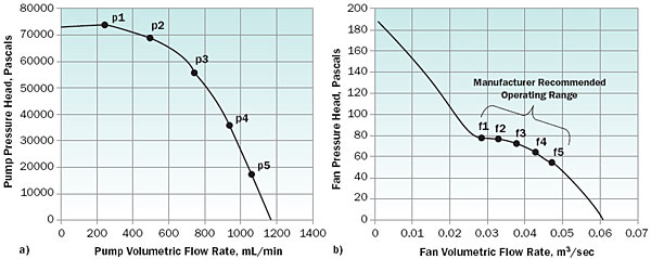 |
Figure 2. Pump and fan curves for commercially available devices used in the illustrative example [6, 7].
Microchannel Cold Plate Analysis
Figure 3a shows the variation of the total microchannel thermal resistance with fin (channel) density in fins/mm, for one of the five pump operating points (p3) from Figure 2a. Very small and very large values of the fin density yield high values of thermal resistance, the former due to limited surface area, and the latter caused by the highly inefficient thin fins. An intermediate geometry can thus be identified which minimizes the thermal resistance, for the two criteria, namely, thermally optimal, and manufacturable optimal.
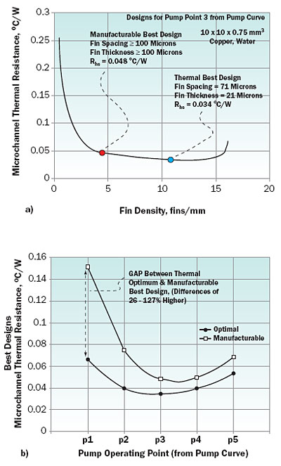 |
Figure 3. Optimization for the microchannel cold plate: (a) identifying the ideal and practical solutions for a single pump point, and (b) quantifying the manufacturability “gap” for the pump curve.
Figure 3b shows the thermally optimal microchannel resistance and the best manufacturable values for all the five pump operating points (see Figure 2a). From Figure 3b, it may be seen that the “manufacturability gap” in performance ranges from 26% to 127%, with the smallest difference observed for pump operating point p4 and the largest for pump point p1. It is also evident from Figure 3b that there exists a minimum globally lowest value for the microchannel thermal resistance for the given pump curve (Figure 2a) and some liquid-side assumptions. The range of fin efficiencies for the optimal and manufacturable designs for the p1-p5 operating point range varies from 0.3-0.67 and 0.97-0.67, respectively.
Heat Exchanger Core Analysis
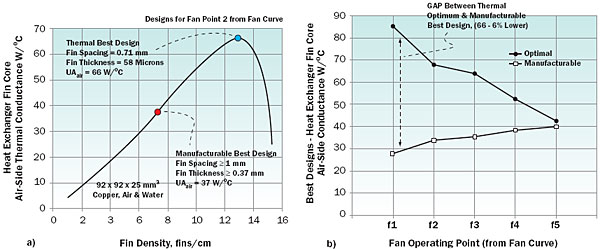
For electronics cooling applications, the air-side conductance is almost always the most important component of the total thermal conductance of a liquid-to-air heat exchanger. The reason for this is that due to space, noise, cost, weight, and other constraints, the size and performance of fans used for cooling commercial electronics are limited compared to other applications such as in automobiles. Thus, the optimization of the fin core geometry will often lead to the best heat exchanger design. Figure 4(a) displays the variation of the air-side conductance of the heat exchanger fin core with the fin density in fins/mm, for one of the five fan operating points (f3) described in Figure 2(b). Analogous to the microchannel analysis shown in Figure 3(a), an intermediate geometry can be identified which maximizes the thermal conductance for the two criteria, namely, thermally optimal, and best manufacturable. The heat exchanger core is assumed to have the same frontal area (92 x 92 mm2) as the axial fan [7] considered. On the application of the manufacturing restrictions, the air-side fin core conductance drops from an optimal value of 66 W/�C to 37 W/�C, a decrease of 44%.
Figure 4(b) quantifies this reduction in thermal performance between the ideal and practical designs for all the fan operating points: from f1 (higher pressure head, low flow) to f5 (lower pressure head, high flow). For the ideal case, the best thermal design occurs at f1, while the best manufacturable design occurs at fan point f5. The reason for this disparity is that the optimal fin thickness and pitch both increase as the fan operating point shifts from f1 (higher pressure head, low flow) to f5 (lower pressure head, high flow). While this change in optimal geometry, to thicker fins spaced further apart, makes the design thermally inferior, it also makes the manufacturable designs closer to the thermally optimal solutions. The fin efficiencies for the optimal and manufacturable designs for the f1-f5 operating points range from 0.77-0.98.
Figure 4. Optimization for the heat exchanger core: (a) identifying the ideal and practical solutions for a single fan point, and (b) quantifying the manufacturability “gap” for the fan curve.
System Analysis
The component-level optimization carried out above for the microchannel heat sink and the heat exchanger fin core can help identify ideal and manufacturable system designs. Although an optimal design exists for the microchannel geometry, the system thermal resistance as defined in equation 1 is also a function of the heat exchanger total conductance, the minimum fluid caloric conductance and the ratio of the fluid caloric conductances. Thus, to optimize for system performance, it is necessary to combine the best microchannel designs for the five pump operating points (p1-p5), with the five best fin core designs for the five fan operating points (f1-f5). Figure 5 shows a bar graph for the total system thermal resistance, Rsystem, as defined in equation 1 for the 25 possible “thermally best system designs” and the “best manufacturable designs”.
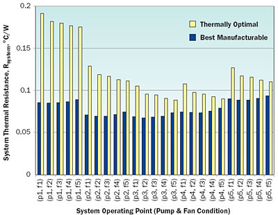 |
Figure 5. System thermal performance (Rsystem) for thermally optimal and manufacturable designs.
The thermally optimal system design occurs at pump and fan operating points p3 and f3, yielding a total system thermal resistance of 0.068�C/W, translating to a heat transfer rate of 443 W based on a 30�C temperature difference between the cold plate base and the inlet air. In terms of the relative contributions of the different components, referring to equation 1, the Rhs, the Rhr, and the [1/f Cpf] terms take values of 0.034, 0.053, and 0.019�C/W, respectively.
In comparison, the best manufacturable design occurs at p3 and f3, yielding Rsystem of 0.089�C/W and a 339 W heat removal rate for a 30�C base-to-ambient air temperature excess. The best thermally optimal design is better than the best manufacturable design by 30%, 233%, and 27% on the basis of heat dissipation rate (W), and heat removal per unit system mass (W/kg), and system Coefficient of Performance (COP), respectively. The system mass is calculated as the sum of the cold plate, heat exchanger, pump, and fan masses.
Summary
A system design model and methodology has been demonstrated to enable thermal optimization with and without manufacturability constraints for a hybrid liquid-air cooling system that includes a microchannel cold plate, a heat exchanger, a pump, and a fan. Optimal system designs with and without such constraints have been presented to quantify the “gap” between ideal and practical solutions. Thermally optimal designs have been shown to dissipate 30% more heat than practical designs, thus quantifying the manufacturability “gap” for a specific example. Analysis has been carried out for copper microchannel cold plate and heat exchanger materials with water as the liquid-side coolant, and with a commercial pump and fan used as fluid-moving devices.
References
- Sobhan, C. and Garimella, S., “A Comparative Analysis of Studies on Heat Transfer and Fluid Flow in Microchannels,” Microscale Thermophysical Eng. Vol. 5, 2001, pp. 293-311.
- Copeland, D., “Review of Low Profile Cold Plate Technology,” ElectronicsCooling, 2005, Vol. 11, No. 2, pp. 14-18.
- Simons, R., “Estimating Temperatures in a Water to Air Hybrid Cooling System,” ElectronicsCooling, May 2002, Vol. 8, No. 2, pp. 8.
- Iyengar, M., and Garimella, S., “Design and Optimization of Microchannel Cooling Systems,” Thermomechanical Phenomena in Electronic Systems -Proceedings of the Intersociety Conference, v 2006, Tenth Intersociety Conference on Thermal and Thermomechanical Phenomena and Emerging Technologies in Electronic Systems (ITherm), May 2006, pp. 54-62.
- Iyengar, M., and Bar-Cohen, A., “Design for Manufacturability of Forced Convection Air Cooled Fully Ducted Heat Sinks,” ElectronicsCooling, August 2007, Volume 13, No. 3, pp. 12-18.
- Extech Pumps, http://www.extech.com.au, Pump number 07012-20.
- EBM-Papst Fans, http://www.papstplc.com, DC Axial Fan Series 3200J.
- Website for Matlab software, www.mathworks.com.

