Introduction
Heat pipes are well-established two-phase devices used in the electronics cooling industry to transport heat from the point it is generated to the place where it is extracted from the system. Three wick structures are most commonly used to provide the capillary path for the liquid return to evaporation section; these are sintered powder, screen mesh and grooved pipes. Although the sintered heat pipe is the most common in the commodity products market including laptop computers, servers and desktop products, the grooved heat pipe is used primarily in space applications. The screen mesh heat pipe has, to date, not achieved the popularity of the other designs.
Screen mesh, one of the oldest wick structures used for heat pipes, has been used since 1964 when Cotter and Grover [1] first published articles about heat pipes as they are known today. However, with today’s requirements of higher power handling and reduced space available, mesh heat pipes are becoming a more attractive option for certain demanding military and medical/analytical applications. This article addresses two application requirements � lifting height and low values of dT (source to ambient temperature difference) � which can be satisfied when screen mesh heat pipes are properly engineered.
Theory of Screen Mesh as Wick Structure for a Heat Pipe
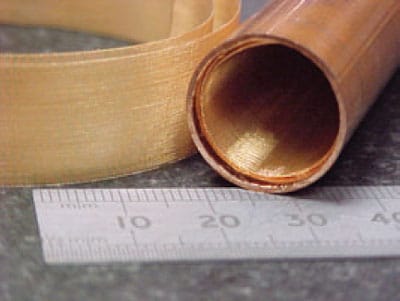
In designing a screen mesh heat pipe (Figure 1), the same basic considerations apply as for sintered heat pipes, i.e., the compatibility of working fluid with the container material and wick material. Groll et al. [3] offer a very comprehensive guide on compatibility of materials and different types of heat pipes while Garner [4] gives an overview of operational limits of heat pipes as well as the three different wick structures and various applications. Zagdhoudi et al. [5] provide a more recent overview of heat pipe applications in the electronics cooling industry. It gives the impression that the lifting height of the mesh heat pipe is inherently less than that of sintered heat pipes. However, this is only true when relatively coarse meshes are used.
 |
Figure 1. Picture showing internal construction of a mesh heat pipe.
This article explores the relationship of mesh size to lifting height and shows that the lifting height can be significantly increased with the use of finer meshes. Various screen mesh types can be used as a wick for a heat pipe. The main screen characteristics are the mesh number and the wire diameter. Resulting from these two, the aperture (opening width) can be obtained either by information from the manufacturer or calculated. The wire diameter and the aperture then influence the average pore radius, which is a unique characteristic for each screen mesh type. The lifting or capillary height for a certain wick/working fluid combination can be obtained from the average pore radius. This is based on earlier work presented Kozai et al. [6] and Imura et al. [7] and correlates very well with experience of the author where screen mesh heat pipes of a higher mesh number were the only solution to transport a set amount of heat within a tight space given.
Equation 1 shows how the lifting or capillary height can be obtained; Table 1 shows a comparisons of the lifting/capillary height for six different wick types, four different meshes and two different sinter powder types. In all six cases, water was used as the working fluid.
Within this equation, H is the capillary or lifting height, and &# 947; is the surface tension [N/m], which is a unique characteristic for each working fluid at certain temperatures. Also, the contact angle Θ [rad] differs for each working fluid, and rc, the effective capillary radius[m], is a unique characteristic of the wick type used. The gravitational support g [m/s2] can be assumed as constant for this equation while the working fluid density ρ1 [kg/m3] depends on the application conditions. Using the equation above and additional ones proposed by Kozai and Imura [6,7], as well as proprietary information for the two different sintered powders has yielded the results in Table 1.
Table 1. Calculated Porosity, Effective Pore Radius and Lifting Height [both m]
|
|||||||||||||||||||||||||||||||||||
From the last row of Table 1, it can be seen that screen mesh wicks do provide a lifting height and screen mesh heat pipes work without gravitational support. Thus, screen mesh heat pipes work against gravity as long as 1) the pipe is reasonably short and 2) its vertical length/height when tilted is below the lifting/ capillary height for the particular mesh deployed.
From the larger vapor space due to the thinner wick, the screen mesh heat pipes achieve their higher power handling capability when the same diameter container is used. This must be sustained by the evaporator length so that heat fluxes are never above the critical values for the wick type used. For standard sintered heat pipes the heat flux limit is typically around 50W/cm2. With more specialized design approaches, combining special powder types with a particular shape of the wick structure, heat fluxes up to 250W/cm2 can be achieved. For grooved heat pipes the heat flux limit is generally relatively low due to the reduced surface area provided for evaporation (around 5W/cm2). Screen mesh wicks can typically handle between 10 and 15W/cm2 so the evaporator and condenser design needs to allow the use of this type of heat pipe [5,8]
Particular attention must be paid if application specific bends have to be added to the pipe design. There are some common rules for all heat pipe types, such as minimum bend radius achievable due to collapsing container material, but in general both heat pipe types, sintered and mesh, need to be treated completely differently. Although sintered heat pipes can be changed in shape without having to consider this at the manufacturing stage and can even support bending after the sintering process due to the much softer container material, screen mesh heat pipes need much more attention.
The main issue is to retain the screen mesh wick aligned at the wall; the harder pipe material is only a minor issue. Various approaches for retaining the wick at the wall can be employed. These range from cutting the wick in a way that allows it to stretch without the wires running along the axis of the pipe, to inserting a spring of a compatible material within the section of the bend in order to prevent the wick from collapsing. A third approach involves insertion of a foreign material, which provides further internal resistance during the bending process and is removed at a later stage.
Experimental Comparison of Different Wick Structures
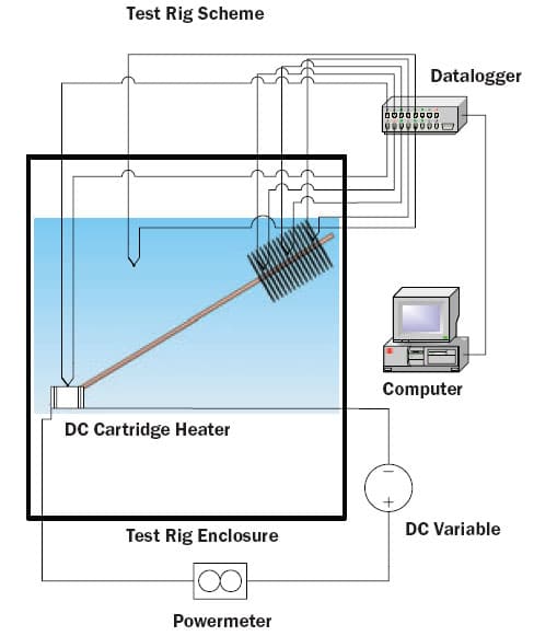
Experimentation was carried out on an assembly (Figure 2) containing a long thin heat pipe and a natural convection fin stack on the opposite end of heat entrance; results are shown in Figure 3. For all results of an equivalent design, in terms of pipe diameter and fin dimensions shown, the length to diameter ratio of the heat pipe was greater than 75 and the number of fins as well as the material and attachment method was kept the same for all assemblies. The fluid charge was varied from wick structure to wick structure to account for the varying porosities of different wick structures.
 |
Figure 2. Schematic picture of test rig with unit at medium test angle.
A further attempt in reducing the fluid charge to compensate for the different lifting heights was undertaken where technically feasible since the power-handling of this pipe was not the most critical parameter but rather a low dT. This approach differs from what was stated by Peterson [2] but the requirements for the heat pipes presented are different from what is required for almost 90% of all heat pipes. Peterson states that heat pipes get deliberately overcharged by manufacturers between 10 and 20% above their nominal fill saturating the wick structure with working fluid in order to avoid dry-out.
For applications where the power handling with minimum material usage is the ultimate criterion, the statement on overcharging is true. In the case described below, stable start up of the heat pipe and low system dT were more critical. In addition, heat fluxes were below critical values for dry-out considerations. Therefore, it was possible to operate at a lower fluid charge in order to avoid collection of working fluid at the evaporator end at higher tilt angles.
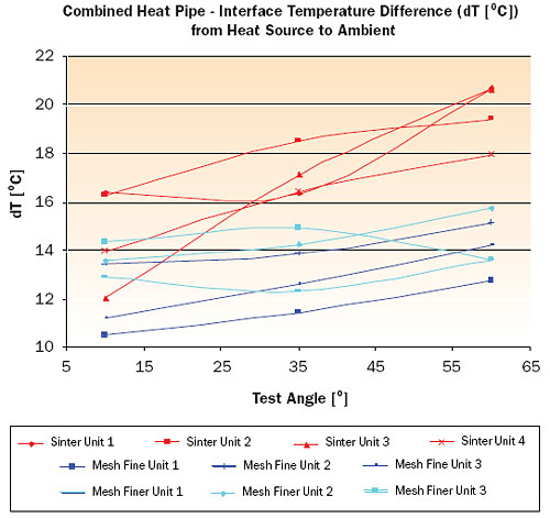
The dT mentioned is measured between a point at the very bottom end where a heat load was simulated by a heater cartridge and the ambient temperature measured adjacent to the fin stack. It consisted of the heat pipe’s dT as well as the dT of the air side (fins to air, interface between heat pipe and fins and spreading within the fins). In order to eliminate further variables the ambient temperature in the test room was controlled to 20�C. Once a unit was set up in the test fixture, three different angles were investigated to mimic the systems possible operational conditions, which could contain any angle in between the minimum and maximum angle. For the ten test samples the dT values in �C against the inclination angle for a fixed heat load are reported in Figure 3.
From Figure 3 it can be clearly seen that nearly all assemblies suffer from reduced fin efficiency due to higher tilt angles. Moreover it can be seen that in this particular application both screen mesh heat pipe variances provide a lower dT than the sintered heat pipe. From these tests the fine mesh was chosen as most suitable for this application because it suffers least from change of operational angle and lowest overall dT with least variation.
 |
Figure 3. Test results for finned assembly with three different wick types and operational angles.
Conclusion
Screen mesh heat pipes can offer a very attractive solution for niche markets where it is important to solve a thermal problem within tight constraints, such as space, weight or low dT. This is mainly the case in the military and medical/analytical markets rather than consumer products. Screen mesh heat pipes need to be well engineered to suit each particular application and to meet its unique requirements. Developing a solution around screen mesh demands the design engineer take a different focus than that used when developing the same solution with a sintered wick, for example. Once this is done screen mesh heat pipes offer a well proven technology capable of delivering certain unique advantages to the market place.
References
- Cotter, T., Grover, G., and Erickson, G., “Structures of Very High Thermal Conductance,” Journal of Applied Physics, Vol. 35, No. 6, 1964, pp. 1990-1991.
- Peterson, G., “An Introduction to Heat Pipes: Modelling, Testing and Applications,” First Edition, John Wiley & Sons, Inc. New York, 1994.
- Groll, M., et al, “Thermal Control of Electronic Equipment by Heat Pipes,” Rev. Gen. Therm., Vol. 37, 1998, pp. 323- 352.
- Garner, S., “Heat Pipes for Electronics Cooling Applications,” ElectronicsCooling, Vol. 2, No.3, Sept. 1996, https://electronics-cooling.com.
- Zagdhoudi, M., Tantolin, C., and Godet, C., “Use of Heat Pipe Cooling Systems in the Electronics Industry,” ElectronicsCooling, Vol. 10, No. 4, Nov. 2004, https://electronics-cooling.com.
- Kozai, H., Imura, H. and Ikeda, Y., “The Permeability of Screen Wicks,” JSME International Journal, Vol. 34, 1991, pp. 212- 219.
- Imura, H., Kozai, H., and Ikeda, Y., “The Effective Pore Radius of Screen Wicks,” Heat Transfer Engineering, Vol. 15., No. 4, 1994, pp. 24- 32.
- Reay, D. and Kew, P., “Heat Pipes,” Fifth Edition, Elsevier, London, 2006.


