Introduction
As power densities of embedded electronics increase, cooling becomes a challenge especially in harsh environments. Liquid cooling is accepted as an attractive cooling method for an increasing number of applications. Direct spray is a particularly efficient form of liquid cooling that has recently been included on several manned and unmanned military platforms. This article will focus on the thermal characteristics of direct spray and platform-level Size, Weight and Power (SWaP) benefits derived from a two-phase cooling approach.
Payload Trends
For decades military platforms have included electronics for avionics, vehicle controls, radios, radar, sonar and fire control. Because of their modest computational capabilities, most of these systems could be implemented with relatively low power devices. There have always been higher performance electronics for applications such as radar processing; Intelligence, Surveillance, and Reconnaissance (ISR) processing; and mission computing. However, high performance electronics were relegated to stationary, benign environments. Due to bandwidth limitations of secure communications between command centers and front line troops, trends to include these computationally intense applications on vehicles and aircraft exist. The military is deploying systems with incredible performance in harsh environments.
At the high temperature end of the range, there is the Medium Extended Air Defense System (MEADS), a surface-to-air missile launcher mounted on a 5-ton truck, used in scorching +60oC deserts. At the low temperature end of the spectrum, there are airborne platforms such as the U-2 Dragon Lady and Global Hawk operating at up to 70,000 feet and -65oC. To fit on these military vehicles, the SWaP characteristics of the electronic systems are minimized to extend the range of airborne platforms or allow ground vehicle transport with a wider range of operation. Direct spray systems are enabling these programs with minimal SWaP budgets to operate in harsh environments using lower cost, high performance embedded electronics.
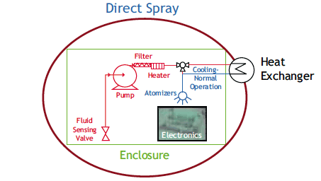
Figure 1. System diagram of direct spray enclosure.
Cooling System Architecture
In practice, direct spray systems operate similarly, independent of shape, size, or application. Figure 1 diagrams the common components found in direct spray enclosures. For all these systems there are three fundamental functions of a cooling system: Heat acquisition, heat transport and heat rejection. Heat acquisition is accomplished by spraying a fine mist of non-conductive and noncorrosive coolant with atomizers (orifices) directly onto electronics or within a cold plate. As the coolant vaporizes, heat is transferred from the electronics to the fluid-vapor mixture. Transport occurs when the coolant vapor condenses on the enclosure walls collecting in the reservoir. System components are often connected by dripless “quick disconnect” fluid connectors for ease of maintenance or reconfiguration. Finally, heat rejection is accomplished via the heat exchanger that rejects the thermal load to ambient air or platform fluid. Several fluid options for heat rejection on military vehicles include Polyalphaolefin (PAO), fuel, engine bleed air, an ethylene glycol and water (EGW) mixture, or ram air. Heaters are also used to warm the electronics at cold ambient temperatures.
Filtration is built into the enclosure, pump and coolant delivery system to remove organic and chemical contamination. For mobile applications, a sump in the center or valves are placed in the corners of the units to sense fluid and open when sufficient fluid is present. A controller is employed to operate the cooling system and provide cooling system status. Lastly, direct spray enclosures support industry standard 6U electronics cards in either conduction or lower cost air-cooled variants.
Thermal Characteristics
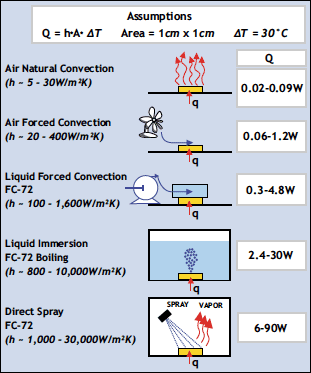
Direct spray enclosures apply fluid directly on the electronics by pumping fluid from the reservoir to the electronics. By wetting the electronics directly, energy is transferred between heat generating components and the fluid via forced convection (sensible heat), evaporation and nucleation (latent heat). The goal is to maximize the phase change from fluid to vapor because of the exceptional heat transfer capacity afforded by the latent heat of vaporization. The differences in heat transfer capacity of a given single phase liquid; boiling and direct spray are shown in Figure 2. Noticeably, direct spray outperforms boiling at higher temperature differences between the component surface and saturated fluid. This is primarily due to direct spray droplet velocity that reduces the boundary layer on component surfaces and breaks up bubbles created by nucleation. Cooling with single phase liquid has significantly less heat transfer capacity than either boiling or direct spray because there is no phase change.
Figure 2. Comparison of cooling methods.
To compare and contrast the cooling capability of direct spray to that of other cooling methods, Figure 2 assumes a 1cm2 device that is 30oC higher than the heat transfer fluid (be it air or liquid). Typical heat transfer coefficients on the left side of the figure determine the amount of power removed from the component (Q) shown on the right side. The differences in cooling capacity are easily explained with fluid properties. The specific heat of air and perfluorocarbon are very similar at 1 kJ/kg-oC and 1.1 kJ/kg-oC, respectively. However, when changing phase, the latent heat of FC-72 is 87.9 kJ/kg contributing to significant heat transfer rates. It is noteworthy that a 30oC temperature difference is difficult to achieve with liquid immersion as bubbles from vapor generation prevent fluid contact with the component surface resulting in a ‘dry out’ condition.
A resistance model is necessary to quantify differences between conduction cooling and direct spray. Typical values for conduction resistance values for spreader-to-wedgelock* range from 0.3 to 0.5oC/W compared to direct spray resistances of 0.1 to 0.3oC/W for similar areas. The resultant temperature difference between heat source and ultimate heat sink (such as ambient air) is 10-15oC higher with conduction than direct spray. This means that the end user with direct spray has the ability to either run at higher ambient temperatures, higher power devices, or both without impacting component reliability.
*Note: wedgelocks are the mechanical device used to secure a conduction cooled circuit card assembly into a ANSI/VITA standard card cage/enclosure.
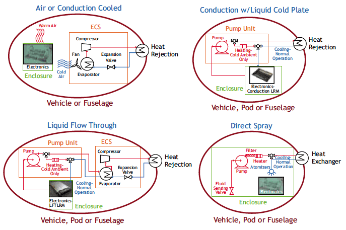
Figure 3. Architectural diagrams for alternative cooling solutions.
Platform Level Comparisons
Heat transfer rates and thermal resistances of a given cooling solution have a direct impact on the available options for fielding electronics in harsh military environments. If sufficient conditioned (air conditioned and/or pressurized) space exists, air-cooled enclosures are a logical choice. When electronics must reside in unconditioned (especially high altitude) environments, conduction-cooled systems are limited in total slot count and constrained to 20-75 W/slot for 6U systems.
As power densities for 6U VPX range from 50-200 W/slot, liquid cooling is an essential supplement to electronics cooling products. The search for fluids that are both non-conductive and possess high sensible heat transfer rates is ongoing. For now, single phase liquid cooling such as liquid cold plate (LCP) and liquid flow thru (LFT) most often employs potentially conductive fluids such as EGW or PAO that create contamination, corrosion and electrical shorting risks.
As the most common approach to electronics cooling, air cooling provides an effective solution when environmental isolation is provided at some level. Figure 3 illustrates a typical platform hosting electronics subsystems. The platform could be an unmanned aerial vehicle (UAV), tracked vehicle or manned airborne application. To remove heat from the electronics in an air-cooled enclosure, air is forced over hot components. Power densities are limited to 150W per single slot 6U VME style board.
The waste heat is dumped to the internal air space and then rejected outside the vehicle to the ambient. On military platforms, there are many options for transferring heat to the ambient such as fuel prior to the engine, PAO, EGW mixture, ram air or ambient air, and to the skin of aircraft or the hull of a ship or submarine. The mechanism often required with air-cooled systems is an environmental conditioning system (ECS) that both pressurizes (for airborne platforms) and cools the air inside the vehicle. Heat removal from the cab or fuselage is the primary role of the ECS. Air-cooled systems have the advantage of using less rugged, lower cost electronics; however, ECS SWaP negatively impacts useful load and/or range of the vehicle. In many airborne pod applications, for example, an ECS is not feasible due to space and weight constraints.
Table 1. Platform-level comparisons of cooling techniques
| Air Conduction Cooled Systems | Liquid Cooled Systems | ||||||
|---|---|---|---|---|---|---|---|
| System Configuration | Sytem Component Description | Conduction Cooled w/o ECS | Air Cooled w/ECS | Conduction Cooled w/ECS | Liquid Cold Plate (LCP) | Liquid Flow Thru (LTF) | Direct Spray Enclosure |
| System Size Compariso | n (Volume – cm³) | ||||||
| Electronics (8 cards/enclosure) | 6U VME Cards | 6U, 160mm (Note 1) | 6U, 160mm (Note 1) | 6U, 160mm (Note 1) | 6U, 160mm (Note 1) | 6U, 160mm (Note 1) | 6U, 160mm (Note 1) |
| Enclosure | 1 ATR short | 15977 | 15977 | 15977 | 15977 | 15977 | 23679 |
| Pump Unit Heat Exchanger | Assume 100 W/slot Heat Rejected to Ambient Air | — | — | — | 5899 3277 | 5899 3277 | Note (2) 5539 |
| ECS | Environmental Control System | – | 975 | 975 | – | 7989 | – |
| Total | 15977 | 16952 | 16952 | 25154 | 33143 | 29218 | |
| System Weight Compari | son (weight – kg) | ||||||
| Electronics (8 cards/enclosure) | 6U VME Cards | 6 | 5 | 6 | 6 | 7 | 5 |
| Enclosure | 1 ATR short | 13 | 9 | 13 | 10 | 11 | 16 |
| Pump Unit | Assume 100 W/slot | – | – | – | 7 | 7 | Note (2) |
| Heat Exchanger | Heat Rejected to Ambient Air | – | – | – | 4 | – | 5 |
| ECS | Environmental Control System | – | 23 | 23 | – | 23 | – |
| Total | 20 | 37 | 42 | 28 | 48 | 26 | |
| System Power Comparis | on (power – W) | ||||||
| Electronics (8 cards/enclosure) | 6U VME Cards | 800 | 800 | 800 | 800 | 800 | 800 |
| Enclosure | 1 ATR short | – | 100 | – | – | – | 90 |
| Pump Unit | Assume 100 W/slot | – | – | – | 120 | 120 | Note (2) |
| Heat Exchanger | Heat Rejected to Ambient Air | – | – | – | – | – | – |
| ECS | Environmental Control System | – | 450 | 450 | – | 450 | – |
| Total | 800 | 1350 | 1250 | 920 | 1370 | 890 | |
Notes:
1 – The volume of the VME circuit cards is accounted for in the total enclosure volume
2 – Pump , controller, valves included in enclosure
Conclusion
When platforms are SWaP constrained, employ low power electronics and are exposed to pressure wash, chemicals, rain, dust, vibration, while operating without an ECS, conduction cooling is a practical solution as shown in Table 1. LCP extends the power density of conduction cooling with minor SWaP impact. With broader industry adoption, LFT offers improved thermal headroom. When electronics power density exceeds approximately 300W/slot, the need for sub-cooled liquid drives additional SWaP on the platform using LFT. Direct spray solutions offer a demonstrated advantage in deploying today’s 20-500W/slot commercial grade or rugged, proprietary or Commercial Off-The-Shelf (COTS) electronics in unpressurized and unconditioned environments. Intrinsic heat rejection flexibility for the integrator is an added value. For enclosure based productions deployed in harsh military applications, direct spray solutions offer significant thermal headroom and provide solid SWaP benefits.


