Introduction
Often in high power density or low profile heat sink applications, the spreading resistances in the base of the heat sink limits the performance of the design. Once it is determined that normal heat sink materials, aluminum or copper, are either insufficient or too bulky to meet the design objectives, the obvious next step is to look at two phase spreading devices, such as heat pipes or vapor chambers. Either technology is often an improvement in these types of applications. The use of vapor chambers offers two distinct advantages over heat pipes, direct contact to the heat source and uniform spreading in all directions.
Heat Sink Integration
Integrating heat sinks and vapor chambers is simpler than most people think and this integration often allows for further improvements in performance.
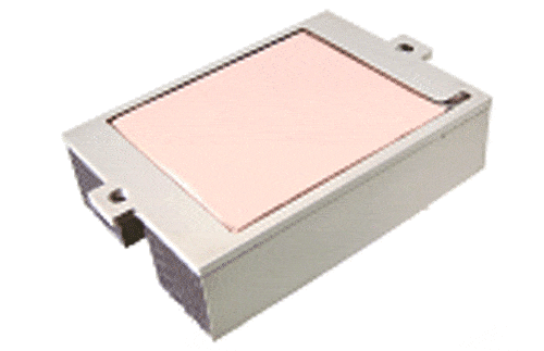
Vapor chambers are integrated into heat sinks using one of several methods. One typical design incorporates three basic parts: the vapor chamber, an aluminum frame for mechanical attachments and a fin pack, which is often made of aluminum. These three parts are soldered into one assembly as shown in Figure 1.
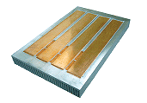
An alternative to this design is to simply add the vapor chambers to the base of an extruded heat sink. In Figure 2, several standard-size vapor chambers are shown imbedded into the base of a large heat sink to provide an isothermal base.
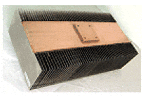
The heat sink in Figure 3, a cooling solution for high-brightness light emitting diodes (HBLEDs), shows how a vapor chamber can be integrated into a fin stack directly.
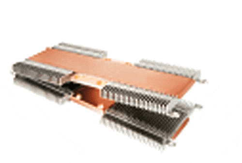
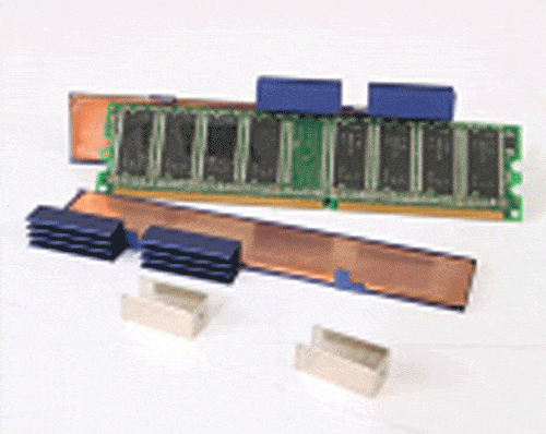
For low profile applications, variants of the designs shown in Figures 1 and 2 are normally used. Figures 4 and 5 show several of these variations.
Thermal Resistance
The most commonly asked question relating to the design of a vapor chamber cooling solution is what is the effective thermal conductivity (W/m-K) of the vapor chamber? Because two phase devices do not exhibit a linear heat transfer behavior, this number is application specific. There are two main resistances within all two phase heat transfer devices: the evaporator resistance and the vapor transport resistance. The third resistance, the condensation resistance, is much smaller than the other two. In the vast majority of applications, the evaporation resistance is the dominate resistance; therefore, making these devices somewhat length independent. This means that a vapor chamber with a transport distance of 75mm will have almost the same Tsource -Tsink as one with a 150mm transport distance. This, in effect, doubles the effective thermal conductivity for the longer devices.
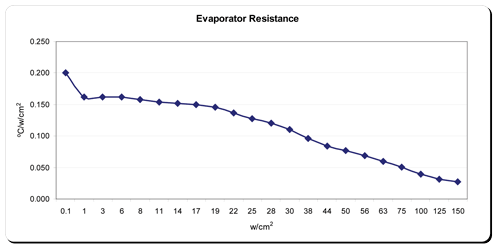
Evaporator resistance is expressed in units of oC/W/cm2. At lower power levels, 5 to 10 W/cm2, this resistance is on the order of 0.1 oC/W/cm2. As power densities increase, the evaporator resistance decreases until a performance limit is reached. This limit can extend to 200 W/cm2 and higher, depending on the vapor chamber design.
Figure 6 shows the evaporator resistance for one particular vapor chamber design.
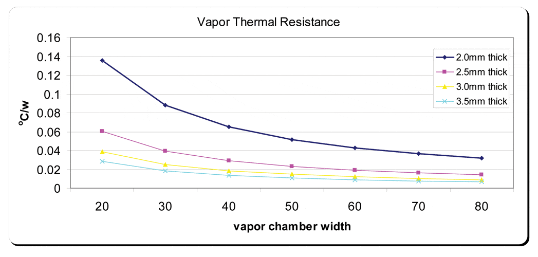
The vapor transport resistance is expressed in similar terms, but refers to the cross sectional area of the vapor space. Keep in mind, changes in temperature or working fluid will change these values. The values presented are typical values for a water-based vapor chamber operating at electronics cooling temperatures. This resistance is 0.01 oC/W/cm2. Figure 7 shows common vapor chamber cross sections of 2.0mm to 3.5mm thicknesses and widths from 20mm to 80mm. The cross sections are calculated and the terms expressed in simple oC/W for each size.
The performance limits for these passive devices was discussed in reference [1].
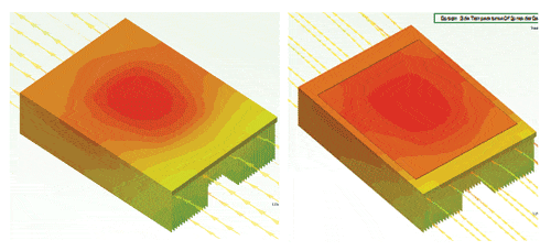
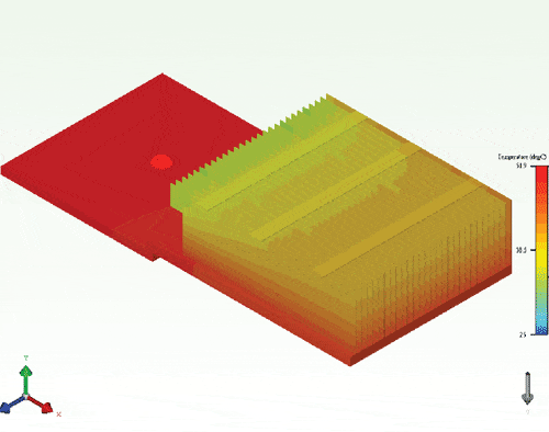
Figures 8 and 9 are examples of thermal models of normal heat sinks and vapor chamber heat sinks.
The thermal models in Figure 8 compare a copper-based 1U heat sink with a vapor chamber-based 1U heat sink. In this type of application, where the heat is being spread uniformly more than it is being transported a long distance, the typical effective thermal conductivities are on the order of 1000 to 1500 W/m-K. In a small form factor such as a 1U heat sink where the transport length is short the effects of the vapor chambers is an improvement of 3oC to 4oC or about a 10% improvement over a copper base. This improvement is often critical in high ambient applications or where the gain is used to lower fan speeds for noise considerations.
The model in Figure 9 shows the heat sink remote from the heat source. In this application, where heat is moved and not just spread the effective thermal conductivities can be more on the order of 5000 to 10,000 W/m-K.
Summary
Vapor chambers are easily integrated into thermal solutions and can offer thermal performance improvements on the order of 10% to 30% over copper and heat pipe based solutions and can often be lighter in weight than equivalent extruded or copper based heat sink. These improvements allow for designers to design for higher ambient or lower noise due to low required fan speeds.
References
1. Garner, S.D., “Heat Pipes for Electronics Cooling Applications”, Electronics Cooling, Vol. 2, No. 3, 1996.
