 Dirk Schweitzer
Infineon Technologies AG
Introduction
The junction-to-case thermal resistance Rth-JC is an important thermal characteristic especially for power semiconductor devices. Its value is often one of the main criteria for the decision whether a device can be used in a specific application and a low Rth-JC is a competitive advantage for the semiconductor manufacturer. However, it must be ensured that the data-sheet Rth-JC value does not underestimate the real value. Accurate and reproducible methods to measure the Rth-JC are required. Unfortunately these requirements are not easy to meet, which is reflected by the fact that to date no JEDEC standard for the measurement of Rth-JC has been defined. The traditional and quasi-standard measurement procedure – referred to herein as “thermocouple (TC) method” – (compare also MIL-STD-883G, method 1012.1 [1]) closely follows the definition of Rth-JC in JESD51-1 [2]: “Thermal resistance, junction-to-case: The thermal resistance from the operating portion of a semiconductor device to outside surface of the package (case) closest to the chip mounting area when that same surface is properly heat sunk so as to minimize temperature variation across that surface.”
Accordingly the thermocouple-method requires the measurement of the junction temperature TJ, the case temperature TC, and the power dissipation P, while the device (according to the above definition) is properly heat-sunk, i.e., in contact with a heat sink. The junction-to-case thermal resistance is then calculated using:

This value shall be referred to herein as “steady-state Rth-JC”, since it is determined under steady-state heat flow conditions.
The measurement of the case temperature is quite prone to errors. A hole or groove in the heat sink must be provided for the thermocouple wires; this however will distort the temperature field and therefore will have an impact on the results. Since the case temperature is non-uniform, the measured temperature depends on the exact position of the thermocouple. Last but not least it is extremely difficult to ensure that the thermocouple actually measures the case temperature and not the temperature of the heat-sink or some value in between. Given these difficulties the reproducibility of thermocouple measurements obtained with one and the same set-up is often surprisingly good – meticulous mounting of thermocouple and device provided – but different measurement set-ups are likely to produce divergent Rth-JC values.
To overcome these problems, transient methods which do not require a thermocouple measurement have been proposed, e.g., by Siegal [3]. While in [3] the problem of determining the thermal interface resistance between package and heat sink remains unsolved, Szabo et al. presented a method to identify the Rth-JC comparing the structure functions obtained by two transient measurements with different interface layers between package and heat sink [4, 5]. Based on their work we have further developed the transient dual interface measurement (TDIM) and propose it now as a JEDEC standard for power semiconductor devices with heat flow through a single dominant path as in heat-slug or exposed pad packages.


MEASUREMENT PRINCIPLE
The TDIM method requires two Zth measurements of the same power semiconductor device in contact with a liquid-cooled heat-sink. Assuming that the chip is heated by a constant power dissipation P which is switched on (off) at time t = 0, the Zth is the change of junction temperature ∆TJ(t) per Watt as a function of the heating (cooling) time t:
Each measurement is performed with a different interface layer between package and cold-plate, causing the two Zth-curves to separate at some point of time (Figure 1). Compared to the TC-method the thermocouple measurement of Tc is not necessary any more, thus avoiding the related problems. We propose to perform one Zth-measurement (a) with a thin layer of thermal grease and the other measurement (b) with no thermal interface material (TIM). The increased interface resistance in case (b) due to the microscopic surface roughness between package and cold-plate ensures a clear separation of the Zth-curves.
DETERMINATION OF Rth-JC
This dual measurement can be evaluated in different ways: One possibility is to convert the Zth-curves into structure-functions and determine the Rth-JC from their point of separation. The accuracy of this approach is limited mainly by the resolution of the NID (network identification by deconvolution) algorithm used to compute the structure-functions [6, 8].
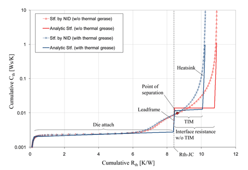
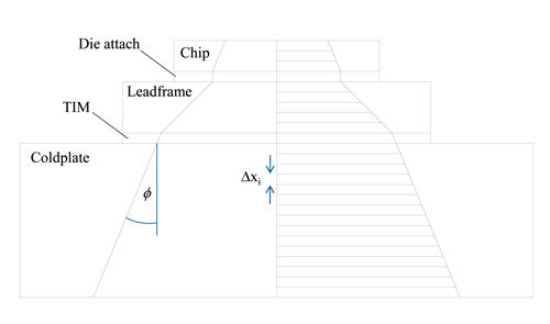
A finite element simulation of the TDI measurement helps to get a clearer picture of the deviations to be expected. Figure 2 shows the cumulative structure-functions obtained by NID of the simulated Zth-curves of an exposed die pad device (curves marked with x or triangles). For comparison the same structure functions have been computed semi-analytically (plain curves), using an approximate model of the heat flow path (Figure 3).
Assuming that the heat flow path can be modeled by a series of truncated cones (thus taking into account the heat spreading), the thermal resistance ∆Rth,i and capacitance ∆Cth,i of the i-th slice of this discretization can be approximated using
∆xi, Ai, ki, ρi, ci being thickness, cross-section, thermal conductivity, density, and specific heat of that slice, respectively. For a small enough ∆xi the cumulative capacitance Σ∆Cth,i of these slices vs. their cumulative resistance Σ∆Rth,i should approximate the actual cumulative structure function well enough for a qualitative analysis. The heat spreading angle φ has been adjusted for each material individually such that Rth-JC and Rth-JA of the semi-analytical model are equal to those of the FE model.
Even though the structure functions obtained by NID are too blurred to reveal the structure of the device accurately, their point of separation is close to its Rth-JC (Figure 2). Or rather: Especially because they deviate from their semi-analytical counterparts, they already separate somewhere in the TIM region, i.e., shortly after the true Rth-JC. Only if the TIM between the package and the heat-sink has a very low Rth (e.g., “liquid metal”) the associated plateau in the cumulative structure function is very small and the cumulative structure functions might already separate before this point.
In the example in Figure 3 the (NID) structure functions separate at Rth = 8.7 K/W whereas the true value is Rth-JC = 8.4 K/W. Unfortunately the error does not scale linearly with the size of the Rth-JC. While for this example an error of 0.3 K/W (3.6%) is totally acceptable, it is not, if the Rth-JC itself is only about this size. Furthermore we observed, especially for devices with a small Rth-JC, that the exact determination of the separation point of the structure functions is often impeded by numerical artifacts produced by the NID algorithm.
For devices with a low Rth-JC we therefore propose another evaluation method similar to the approach suggested by Siegal [3]. This method is based upon a determination of the separation point of the Zth-curves and is only applicable to devices with thermally high conductive die attach (e.g., solder). The starting point is the observation that for these devices the Zth-value at the point of separation is always very close to the Rth-JC of the device (Figure 1).
The somewhat “intuitive” explanation for this is often that “the curves start to diverge when the heat-flow has arrived at the device/heat-sink interface.” While this explanation is not exactly wrong it definitely lacks some precision and shall be investigated more closely.

The temperature difference between any two points A and B within the same solid is always connected with a heat-flow (W) between these points. The temperature gradient at location x = (x, y, z) is
with thermal conductivity k(x) and heat-flux vector p(x, t) (W/m2). If we move by a step ds = (dx, dy, dz) the temperature changes by
Consequently the temperature difference between A and B can be expressed by the path integral
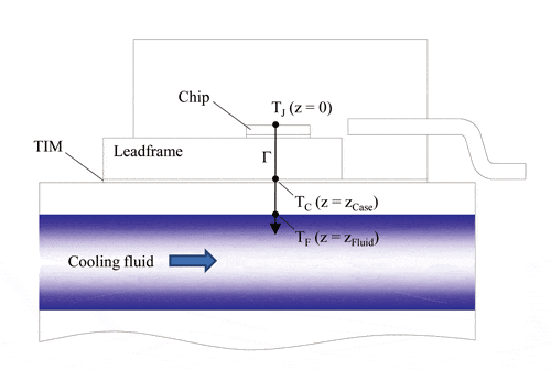
for an arbitrary path Γbetween A and B. Applied to the temperature difference ∆TJF(t) =∆TJ(t) between junction (at z = 0) and fluid (at z = zFluid) for a semiconductor device on a liquid-cooled cold-plate, this means
using the integration path Γ along the z-axis shown in Figure 4 (the minus sign has been dropped here because we are only interested in the absolute value of ∆TJF). For the temperature difference ∆TJC(t) between junction the path integral goes only from z = 0 to z = zCase:
Based on these equations the relationship between Rth-JC and the splitting point of the Zth-curves shall now be investigated. As an example the Zth-curves (Figure 5a), their difference (b), the heat-flux distribution along the z-axis (c), and the temperature gradient (d) have been computed for a MOSFET with solder die attach very similar to the device shown in Figure 4. If we assume that the resolution of a Zth-measurement is 0.001°C/W (e.g., for temperature resolution 0.01°C and power dissipation 10W), the separation of the Zth-curves could be observed earliest at time ts = 0.013s (Figure 5a and 5b). The Zth-value at that point of time is Zth(ts) = 1.06 K/W.
Due to heat-spreading, the heat-flux decreases quickly with increasing distance from the chip surface. Figure 5c compares the heat-flux distributions at time ts = 0.013s (dashed line) and in steady-state (solid line). When the Zth-curves separate, the heat-flux throughout the device has not yet developed its final strength; however there is already a non-negligible flux through the TIM layer between device and cold-plate (this being the reason why the curves start to separate) and even inside the cold-plate.
If the heat-flux p(z) is divided by the piecewise constant thermal conductivity k(z), one obtains the temperature gradient curve (Figure 5d). Again the dashed (solid) line shows the temperature gradient at time ts = 0.013s (steady-state). In this example the thermal conductivities are 148W/mK (silicon), 50W/mK (solder), 350W/mK (Cu), 1.2W/mK (thermal grease), and 350W/mK (Cu) in the chip, die-attach, leadframe, TIM, and cold-plate region, respectively. According to equations (7) and (8) the total temperature increase ∆TJ (t) = ∆TJF(t) equals the total area under the gradient-curve whereas the temperature difference ∆TJC(t) between junction and case corresponds to the partial area in the range [0, zCase].
Figure 5c + d illustrate the following: At time ts, when the Zth-curves start to diverge, the heat-flux has nowhere yet reached its final strength. The resulting temperature difference ∆TJC(tS) between junction and case at that time is therefore lower than in steady-state: ∆TJC(tS) < ∆TJC(t = ∞). But a comparison of the corresponding areas under the gradient-curves in Figure 5d shows that the deviation between ∆TJC(tS) and ∆TJC(t = ∞) is quite small. This deviation is compensated (in this example over-compensated) by the additional contribution of the TIM layer to the measured ∆TJ(ts) at time ts (area under the TIM peak in Figure 5d). Therefore we can use the following approximation to determine Rth-JC:
or
As mentioned above this approximation cannot be applied if the device contains an internal barrier to the heat-flow, such as a thermally low conductive glue die-attach. In that case the two Zth-curves might separate “too early”, i.e., the Zth-value at the point of separation can be considerably smaller than the Rth-JC of the device: Zth(ts) < Rth-JC [7]. The explanation is that an internal heat-flow barrier delays the increase of the heat-flux inside the device, i.e., the difference between the heat-fluxes at time ts and in steady state becomes bigger. In the region of the thermally low conductive layer the heat-flux difference causes also a higher difference between ∆TJC(tS) and ∆TJC(t = ∞) due to the larger factor 1/k in integral (8).
ACCURACY CONSIDERATIONS
The accuracy of approximation (9) depends on many factors: the resolution of the Zth-measurement which determines the point of separation, the thermal conductivity and thickness of the materials inside the device, and the thermal resistance of the TIM layer between device and heat-sink. Even the thermal resistance of the cold-plate has an influence on the resulting Rth-JC. All these influencing factors must be standardized as far as possible in order to ensure the reproducibility of the transient Rth-JC measurement. Some factors such as the thickness of the thermal grease cannot be controlled, which puts a limit to the achievable accuracy and reproducibility of the TDIM method. An estimate of the measurement error for Rth-JC is difficult since no reliable reference values exist. The traditional thermocouple measurement is too inaccurate to serve as a reference. In most cases the measured Rth-JC values could be confirmed by finite element simulations within ±15% or better. Repeated Rth-JC measurements of the same device are usually reproducible within at least ±5%. For the simulation example above the steady-state Rth-JC is Rth-JC = 0.99K/W, whereas Zth(ts) = 1.06 K/W, i.e., the Rth-JC is over-estimated by 7%.
One can easily imagine that even a small vertical shift of one of the Zth-curves of the dual interface measurement can have a big influence on the position of the splitting point. Such a shift can be caused by a wrong offset correction of the Zth-curve. In practice it is therefore advantageous to determine the point of separation from the derivatives of the Zth-curves; that way a constant offset has no influence on the result [8]. A distance ɛ should be defined as separation criterion: the point of separation is the smallest time ts for which the difference of the derivatives is ≥ ɛ. The correct value for ɛ can be determined by finite element simulations, see [8] for a detailed description.
CONCLUSIONS
For power semiconductor packages with a single dominant heat flow path (heat-slug and exposed die-pad packages) the transient dual interface measurement is an alternative to the traditional thermocouple measurement of Rth-JC with higher accuracy and reproducibility.
REFERENCES
MIL-STD-883G, United States Department of Defense Test Method Standard: Microcircuits, Method 1012.1 Thermal Characteristics, 1980.
Electronic Industries Association, Integrated Circuit Thermal Measurement Method – Electrical Test Method, EIA / JEDEC Standard, JESD51-1, 1995 [www.jedec.org].
Siegal, B., “An Alternative Approach to Junction-to-Case Thermal Resistance Measurements,” ElectronicsCooling, Vol. 7, No. 2, 2001, pp. 52-57.
Szabo, P., Steffens, O., Lenz, M., and Farkas, G., “Transient Junction-to-Case Thermal Resistance Measurement Methodology of High Accuracy and High Repeatability,” Proc. 10th THERMINIC, Sofia-Antipolis, 2004, pp. 145-150.
Steffens, O., Szabo,P., Lenz, M., and Farkas,G., “Thermal Transient Characterization Methodology for Single-Chip and Stacked Structures,” Proc. 21th SEMITHERM, San Jose, 2005, pp. 313-321.
Schweitzer, D., Pape, H., and Chen, L., “Transient Measurement of the Junction-to-Case Thermal Resistance Using Structure Functions: Chances and Limits,” Proc. 24th SEMITHERM, San Jose, 2008, pp. 193-199.
Schweitzer, D., “Transient Dual Interface Measurement of the Rth-JC of Power Packages,” Proc. 14th THERMINIC, Rome, 2008, pp. 14-19.
Schweitzer, D., Pape, H., Kutscherauer, R., and Walder, M., “How to Evaluate Transient Dual Interface Measurements of the Rth-JC of Power Semiconductor Packages”, Proc. 25th SEMITHERM, San Jose, 2009, pp. 172-179.
Dirk Schweitzer can be reached at dirk.schweitzer@infineon.com


