As far as history goes, the field of electronics cooling does not have a very long past. A rather quick look through my personal reference material that is strictly geared towards cooling electronics had at the earliest some US Navy documents from the 1950s [1]. Comparing the solution techniques available today to those available then shows that we have both much better tools and harder problems (although I still like to refer to the suggested heat transfer coefficient value of ~10 W/m2-K for natural convection when not much else is known). Perhaps because of the shorter history and the tendency of engineers working in this field always being exposed to the latest and greatest electronics, the electronics cooling community sometimes doesn’t venture out and learn from related fields. When we start solving problems without doing significant research, we can live in a fairy tale world where we think that our problems are strictly unique to us. There can be a benefit of taking some time to examine the past and finding out that other smart engineers have often looked at similar problems and may have relevant information that would help us with understanding.

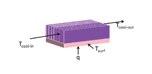
The use of heat exchanger theory provides a good example where there is a possible benefit from thinking about the problems we are solving from more than one viewpoint. Consider the simple illustration of a heat sink shown in Figure 1. Heat sink suppliers and designers, especially in air cooled electronics, like to use a thermal resistance type description such as
Rth = 1/hA = (Tsurf -Tcool-in)/q
Since the resistance can vary with the coolant velocity, information about how Rth varies with velocity may be provided. The coolant temperature of reference is the inlet temperature. While this approach is convenient, there isn’t much need to think about using a minimum amount of coolant and other constraints such as noise and prime power to move the coolant may dictate the flow rate. Engineers that come from an avionics background typically consider that the coolant will change temperature as the waste heat is added. Often, the coolant flow rate is specified in terms of flow rate per KW of heat such that the temperature rise of the coolant from inlet to exit is constant for different electronic assemblies. The mindset is to use the coolant as efficiently as possible because additional coolant is either not possible or very expensive. One of the potential benefits of applying heat exchanger theory to electronics cooling is that it can provide one way of looking at efficiency.

Moffat [2] provides a good discussion on heat exchanger theory applied to air cooled heat sinks and general heat exchanger theory can be found in most heat transfer textbooks [3]. While the theory was mostly developed to deal with two fluids, a bounding case where one of the fluid temperatures did not change (such as with condensation or evaporation) simplifies the equations and can be representative of heat sinks used to cool electronics. A uniform temperature for Tsurf is only an approximation but useful for illustration. Heat exchanger analysis frequently uses what is known as the effectiveness-NTU method where the effectiveness represents the actual heat transfer divided by the maximum possible heat transfer. The NTU, or Number of Transfer Units, is a dimensionless parameter that relates the heat transfer convective resistances to the coolant flow heat capacity. While the details are beyond the scope of this short column, a typical heat sink (or cold plate) can be described with the following equations (assuming that the simplifying assumption of one surface temperature is reasonable).
1 Actual heat transfer = Ccool*(Tcool-out – Tcool-in);
(Ccool is the mass flow times the heat capacity for the coolant)
2 Maximum possible heat transfer = Ccool*(Tsurf – Tcool-in)
3 Effectiveness = E = (Tcool-out – Tcool-in)/ (Tsurf – Tcool-in)
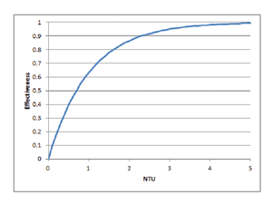
4 Effectiveness = 1 – exp(-NTU), where NTU = hA/Ccool
At this point, someone used to using resistance based concepts for heat sinks might ask why go to all this trouble. The reason for thinking about the problem in these terms is the form of equation 4 which is shown graphically in Figure 2. Note that if we want to increase the effectiveness of our heat sink we need to increase NTU. One way to increase the NTU term is to decrease the coolant heat capacity but while our effectiveness increased, the resulting temperature for the surface may not be acceptable. The other way is to increase the hA term which means either larger area or a higher effective heat transfer coefficient. The engineering challenge is to minimize the decrease in effectiveness as coolant flow rates increase. Note that the limit is when the surface temperature and the coolant exit are at the same temperature, or the system has an effectiveness of 1. This limit is formally only for a constant temperature boundary condition (as opposed to uniform flux or mixed boundary condition) and is only a theoretical maximum, but it does provide a basis for comparison. More complex systems such as cold plates with multiple heat sources or significant coolant temperature variation may require more detail to assess but the general trends are similar. Historical electrical analogy treatment of cold plates (typical in avionics) sub-divides the problem into zones and accounts for the coolant rise but make the assumption that a heat transfer coefficient relative to a local coolant temperature is known. Some heat sink resistance calculations add in a “fluid resistance” but the reader is cautioned that this terminology can be problematic [2].
We are often asked to help design more efficient systems but sometimes the definition of efficient is vague. From the perspective of coolant in and out temperatures, the heat transfer process is 100% efficient and the heat ended up in the coolant. However, the real question may be, can the cooling job be accomplished with a lower flow rate and still have acceptable temperatures? Thermal engineers can participate and even lead discussions on developing even more efficient systems but we benefit when we look at problems from multiple viewpoints and even venture out into the research from related fields.
References
Bureau of Ships NavShips 900,190, Guide Manual of Cooling Methods for Electronic Equipment, 1 November, 1956.
Moffat, R, “Modelling Air-Cooled Heat Sinks at Heat Exchangers,” ElectronicsCooling, February 2008.
F. P. Incropera & D. P. DeWitt 1990 Fundamentals of Heat and Mass Transfer, 3rd edition, Wiley, New York. l


