Microchannel cooling has emerged as an effective method to enhance cooling for electronics devices [1]. However, the problem of boundary layer development, as liquid coolant travels downstream, persists in conventional microchannel heatsinks. Consequently, convective heat transfer performance of a heat sink deteriorates in the axial direction, resulting in elevated maximum temperature, and significant temperature gradient, across the heat sink. A heat transfer augmentation scheme is therefore beneficial for a microchannel heat sink.
A simple configuration of oblique cuts on the straight fins is developed to enhance the performance of the conventional heat sink [2]. The segmentation of continuous fin into oblique sections leads to the re-initialization of boundary layers at the leading edges of each oblique fin, effectively reducing boundary layer thickness. This regeneration of entrance effect causes the flow to maintain a thermally developing state throughout the channel, thus resulting in better heat transfer. In addition, the smaller oblique channels divert a small fraction of flow into the adjacent main channels [3]. The secondary flow thus created improves fluid mixing, which further enhances heat transfer. A pressure recovery effect is also noticed in the diffusive oblique channel, which minimizes the pressure drop penalty for the increased heat transfer.
Boundary Layer Redevelopment

The comparison of the enhanced oblique and conventional straight microchannels is shown in Figure 1. To understand the mechanism of enhancement of oblique technology, numerical simulation is carried to study the fluid flow and heat transfer characteristics. For a fair comparison, the straight microchannel share the same dimensions as the enhanced oblique microchannel with the exception of the oblique cuts on the continuous fins, i.e., similar channel aspect ratio, channel width, fin width and overall footprint.
Evident from Figure 1(a), the oblique fins structure exhibits spanwise periodicity if the edge effect is neglected. In the numerical simulation, the channel width (wch), height (H) and fin pitch (p) are set to be 0.5 mm, 1.5 mm and 2 mm, respectively. The flow at a periodic boundary is treated as though the opposite periodic plane is a direct neighbor to the cells adjacent to the first periodic boundary. Thus, when calculating the flow through the periodic boundary adjacent to a fluid cell, the flow conditions at the fluid cell adjacent to the opposite periodic plane are used [4]. Both simulation domains for enhanced microchannel and conventional microchannel are generated using a general purpose CFD preprocessor [5]. The simulations are executed with a general purpose commercial CFD software [6], which solves the four governing equations numerically. These governing equations consist of continuity equation, momentum equation, energy equation for liquid and energy equation for solids.

Upon exporting the mesh files to the CFD software, the 3D double-precision pressure-based solver is selected with standard SIMPLE algorithm as its pressure-velocity coupling method [7]. Standard discretization scheme is used for the pressure equation while second order upwind discretization scheme is selected for both momentum and energy equations. Water is chosen as the working fluid while copper with constant thermal conductivity is selected as fins and heat sink material. The density, specific heat capacity, thermal conductivity and dynamic viscosity of water are evaluated at the mean fluid temperature [8].
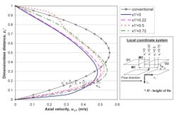
To show the difference of flow conditions in straight and oblique microchannels, the axial velocity profiles are plotted in Figure 2 for the selected typical locations. Fin surfaces are also named specifically (M1, M2, O1 and O2). It is obvious that the segmentation of the continuous fin into sectional oblique fins disrupts the velocity profile and thus the hydrodynamic boundary layer development at the trailing edge of each oblique fin section. The discontinuity with the downstream fin causes the hydrodynamic boundary layer development to restart at the leading edge of the next downstream fin. In addition, the shorter oblique fin limits the development of boundary layer unlike the long continuous fin of the conventional microchannel. These axial velocity profiles of the enhanced microchannel skew towards fin surface M1 at z1’ = 0 in the main channel compared to the fully developed velocity profile of the conventional microchannel, which is symmetrical at the centerline (z1’ = 0.5). Consequently, the oblique fins surfaces M1 at z1’ = 0 plane will have a thinner boundary layer even though the average velocity in the main channel is lower compared to that of the conventional microchannel. On the other hand, the oblique fins surfaces M2 on z1’ = 1 plane have a thicker hydrodynamic boundary layer.

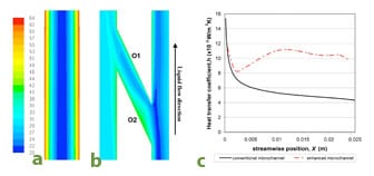
Figure 3(a) displays the water temperature difference between two different structures. It is found that oblique channel presents more uniform fluid temperature distribution between 21 – 43°C compared to 20 – 62°C in the conventional microchannel as shown in Figures 3(a) and (b), due to better fluid mixing. The lower near-wall fluid temperature of the oblique channel translates to a lower channel wall temperature and a subsequently lower device temperature. As suggested by Steinke and Kandlikar [9], the introduction of the oblique channel between the main channels could induce a small fraction of the liquid coolant into it and generate secondary flow, without requiring external power source or incurring a major increase in pressure drop. Subsequently, the injection of secondary flow back into the adjacent main channel disrupts the coolant flow, accelerates the heat propagation into the fluid core and increases the fluid mixing. It is also noted from Figure 3(c) that the initial heat transfer coefficient of the conventional microchannel can be as high as ~15,000 W/m2K. However, it quickly diminishes as the boundary layer thickens when the fluid travels downstream and attains a fairly constant value at ~5,000 W/m2K, displaying a highly non-uniform heat transfer performance from the inlet to the outlet of the heat sink. In contrast, the variation of local heat transfer coefficients for the enhanced microchannel is smaller, with a higher averaged value of ~10,000 W/m2K. The local heat transfer coefficient is observed to increase 100% almost anywhere along the channel. With the more effective heat transfer, 60% more heat flux can be dissipated with the enhanced microchannel if the same maximum wall temperatures are maintained.

Test of Prototype
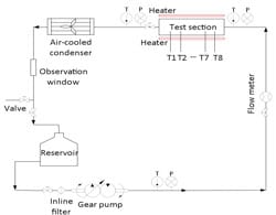
The above numerical results show significant enhancement due to the oblique structure. A liquid cold plate of a footprint 0.04752 m2 and main channel hydraulic diameter of 2 mm with oblique microchannels is designed based on the practical applications for cooling battery packs used in an electronic vehicle. Due to the limitation of available space within the battery pack, an ultra-thin form factor is considered. In order to facilitate a fair comparison, a straight channel liquid cold plate is fabricated with the same dimensions only without oblique cuts on the fins. Figure 4 shows the test system flow diagram. The cooling liquid is driven by the gear pump, through the flow sensor and into the liquid cold plate, where heat transfer occurs. After that, the heated cooling liquid is cooled in the radiator before reaching the reservoir. The flow rate is measured with a flow sensor at the liquid cold plate inlet, while cooling liquid temperature and pressure are measured at both inlet and outlet of the liquid cold plate. Surface temperatures of the heaters installed on both sides of the cold plate are measured by 8 evenly distributed T-type thermocouples.
The total thermal resistance of tested cold plates are evaluated by

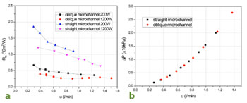
where Tmax and Tout are the surface maximum temperature and liquid outlet temperature. A and Qare the heating area and power. Figure 5(a) shows the calculated thermal resistance for the tested cases. The solid line represents the heating power of 200W while dash line corresponds to the heating power of 1200W. It can be seen that overall thermal resistance of oblique cold plates is much lower than that of straight channel for both power inputs. For the flow rate approximately ranging from 0.3 l/min to 0.9 l/min at 200 W, the averaged resistance of oblique channel is reduced 100% when compared to that of straight channel. For heating power of 1200 W, the thermal resistance of the oblique channel is about 3 times lower than that of the straight channel. It indicates that the ultra-thin cold plate is a good candidate for high heat dissipation. A thermally enhanced microchannel heat sink should possess either better heat removal performance at a given driving power or lower pressure loss for a fixed heat duty. Figure 5(b) shows the pressure drop measured at cold plate inlet and outlet versus inlet flow rate. It is noted that the pressure drop of the oblique channel is similar to that of the straight channel. This implies that the pressure loss penalty for the increased solid-fluid contact area is negligible. As shown in Figure 1, the fluid flow in the secondary channels is induced naturally by pressure difference along the main channels. Compared to the main channel, the friction of secondary flow through the oblique channel is relatively small and does not require additional power. Therefore, the current proposed structure is a promising structure which can reduce the overall thermal resistance significantly while maintaining the pumping power unchanged when compared to the conventional straight microchannel.
Cost of Manufacturing
Prototypes of two different footprints were discussed in the paper. The two footprints require different manufacturing methods. Metal injection molding (MIM) has been identified as a cost effective manufacturing methods for high volume production of the smaller footprint copper prototype. Each liquid cold plate is estimated to cost around 15 USD amortizing mold and assembly costs.
As for the larger footprint aluminum prototype, forging has been identified as a cost effective manufacturing method for high volume production. Each liquid cold plate inclusive of mold cost is estimated to range from 30 USD to 200 USD depending on assembly techniques.
As such, the enhanced oblique fin cold plate is a cost effective alternative to conventional liquid cold plates due to its comparable cost of production coupled with enhanced performance at lower pressure drop penalties.
Conclusions
This article presents a novel structure to enhance convective heat transfer in the microchannel. Based on the analysis and experimental test on the proposed oblique technology, the advantages of using oblique microchannel for electronics cooling are as follows:
1) The oblique structure significantly increases the surface area for heat transfer between the cooling liquid and the solid material.
2) The fluid flow in the secondary channels interacts with the main channel flow causing it to be constantly in the development stage, thereby enhancing the performance of heat transfer.
3) The fluid flow in the secondary channels is induced naturally by pressure difference along the main channels. Due to extremely short flow path of the secondary flow in the oblique cut, the friction loss can be neglected and the system does not require additional power.
4) The oblique structure is simple and easy to apply to practical applications. In addition, cutting oblique slots on the continuous fins reduces the weight of heat sink/cold plate and the cost of material.
5) Metal injection molding and forging can be used to manufacture small and large footprint liquid cold plates respectively at competitive costs.
References
[1] D. B. Tuckerman and R. F. W. Pease, “High-performance Heat Sinking for VLSI,” IEEE Electronic Device Letter EDL-2, pp. 126–129, 1981.
[2] P. S. Lee, S. K. Chou, and Y. J. Lee, “Optimization of the Thermal Performance of Microchannel Heat Sinks Using Thermally Developing Nusselt Number Correlation,” 10th Electronic Packaging Technology Conference, pp. 545-51, 2008.
[3] Y. J. Lee, P. S. Lee and S. K. Chou, “Hotspot Mitigating with Oblique Finned Microchannel Heat Sink,” Proceedings of the ASME International Mechanical Engineering Congress & Exposition, IMECE, U.S., 2010.
[4] Fluent 6.3 User’s Guide, Lebanon, NH, Fluent Inc, 2006.
[5] Gambit, Release 2.3, www.ansys.com.
[6] Fluent, Release 6.3, www.ansys.com.
[7] S. V. Patankar, Numerical heat transfer and fluid flow, Hemisphere Pub. Corp., 1980
[8] F. P. Incropera, Liquid Cooling of Electronic Devices by Single-Phase Convection, Wiley, pp.262-263, 1999.
[9] M. E. Steinke and S. G. Kandlikar, Single-phase Heat Transfer Enhancement Techniques in Microchannel and Minichannel Flows, Proceedings of the 2nd International Conference on Microchannels and Minichannels (ICMM2004), pp. 141-8, 2004.


