SINCE 2008, collaborative research conducted at Raytheon Company, Thermacore Incorporated, Purdue University and Georgia Tech Research Institute has pursued the development of Thermal Ground Plane (TGP) technology. The DARPA-sponsored Radio Frequency Thermal Ground Plane (RFTGP) program focused on the development of high effective conductivity (keff >1000W/mK), low coefficient of thermal expansion (CTE, 5-7ppm/K), thin (1-3mm) heat spreaders for high heat flux (100+W/cm2) cooling. RFTGPs were developed to spread heat from multiple small (10s of mm2) device sources over larger (10s of cm2) areas in high packaging density applications. Efforts focused on the development of CTE-matched vapor chamber designs incorporating high heat flux bearing, low thermal resistance evaporator wick structures. We produced a TGP that provides significantly improved performance relative to state-of-the-art commercial solid conductor solutions used in electronics packaging applications. This article highlights key results from the effort, including scientific findings, new capabilities, practical advantages and limitations associated with the developed TGP technology.
Vapor Chamber Heat Spreaders
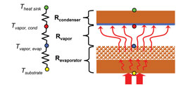
Vapor chambers (sometimes referred to as flat heat pipes) are passive heat transport devices that utilize capillary forces to circulate a working fluid between discrete evaporator and condenser regions. Waste heat from electronic devices affixed to the evaporator is absorbed through vaporization of a working fluid (in this case water) and subsequently rejected to a heat sink or cold plate attached to the condenser. Vapor chambers achieve high effective conductivity by transporting heat via vapor generation and flow, as opposed to conduction. Overall thermal resistance in vapor chamber heat spreaders is comprised of three primary component resistances: 1) evaporator resistance, 2) vapor transport (pressure loss) resistance, and 3) condenser resistance (Figure 1).

Although there are many ways vapor chambers (and heat pipes) can be used, most uses can be classified either as an “active cooling” mode, where the primary focus is X-Y heat spreading, or “remote cooling” mode, where the focus is lateral heat transport [1]. In the “active cooling” mode, the merit of a vapor chamber heat spreader relative to a solid conductor is primarily dependent on the evaporator resistance, geometry (thickness, condenser/evaporator area ratio) and heat sink resistance (HSR) [2]. The HSR is defined by the packaging that separates the cold side of the TGP from the ambient, and can be approximated as the one-dimensional combined conduction and convection resistance from the cold side of the heat spreader to cooling fluid (liquid or air). Careful consideration of these factors for a given application is required to determine whether a solid conductor or vapor chamber solution will provide more effective heat spreading [3]. Ideal “active cooling” vapor chamber applications are those that are thickness-constrained with relatively large condenser/evaporator area ratios. Other considerations, such as a CTE-matching requirement, can also influence the solid conductor/vapor chamber trade-off by limiting solid conductor options to lower conductivity ceramics (e.g., AlN) or metal composites (e.g., CuMo). While a thermal designer can sometimes define or influence geometry or HSR, often minimization of evaporator resistance is the primary opportunity to maximize the benefit achievable with a vapor chamber heat spreader. As such, much of our TGP development effort focused on development of high performance evaporator structures.
State of the Art Sintered Cu Powder and Nanostructured Evaporator Wicks
TGP resistance is heavily influenced by whether evaporative or boiling regimes dominate the vaporization process within the wick. During TGP development, evaporator investigations initially focused on the identification of novel ultra-thin and/or bi-porous wick designs to reduce evaporative resistance. However, for the small heat input areas (5mm x 5mm) and high heat fluxes (100s of W/cm2) investigated, we found boiling to be the higher performing and more desirable regime for TGP operation. This feature is attributable to the “short circuiting” of wick thermal resistance that occurs in the boiling regime (Figure 2). Experimental characterization of sintered Cu powder wicks demonstrated that it was possible to optimize sintered Cu powder wicks for boiling performance [4]. This was followed by investigation into novel wick structures specifically targeted to minimize resistance by promoting nucleate boiling. Two novel wick material systems were developed to maximize TGP performance.

CNT Enhanced Sintered Cu Powder Wick Structures
Due to their controllable nanoscale capillary features and high reported on-axis conductivity, vertically oriented Carbon Nanotubes (CNTs) were explored as a candidate nanowick material. Early in the TGP effort we demonstrated that CNTs (which are naturally hydrophobic) can be rendered hydrophilic through application of an evaporated, conformal Cu coating. However, we also found that the low permeability of CNTs overwhelms the increased capillary pumping, limiting their use to very small evaporator areas [5]. To overcome this limitation, several bi-porous wick design approaches involving selective CNT growth on patterned conventional sintered wick materials were analyzed, with results pointing to significant opportunities to reduce the evaporative resistance [6].

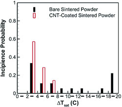
Experimental investigations were undertaken to determine whether these predicted benefits could be realized. While results indicated that some potential enhancement could be achieved in the boiling regime [2], the predicted evaporative benefits proved difficult to quantify due to unforeseen (and beneficial) effects of CNT functionalization on heat transfer regime. In wicks functionalized with CNTs, we observed a significant decrease in the incipient wall superheat (peak temperature on the evaporator surface minus the vapor temperature) required to initiate boiling within the wick [7]. While CNTs had been demonstrated to reduce incipient superheat in pool boiling from flat surfaces [8], to our knowledge, this was the first conclusive demonstration of such a reduction in sintered Cu powder wicks. Moreover, we observed that the CNTs reduced the variability inherent to boiling incipience relative to that observed in sintered powder wicks without CNTs (Figure 3). As such, CNTs provide a means to ensure that the wicks would operate in the boiling regime at lower heat inputs and at lower temperatures than they otherwise would without CNTs (Figure 5). This is a subtle but significant benefit. As shown in Figure 5, the transition from evaporation to boiling heat transfer within the TGP corresponds to a significant improvement in performance.

Cu Foam Wick Structures
State of the art (SoA) Cu powder-based wick structures are typically fabricated by sintering relatively large Cu particles (10s to 100s of microns) in a mold. Particle size and sintering conditions determine wick characteristics (i.e., effective pore radius, permeability, porosity), which largely determine TGP thermal resistance and transport capacity. We found that in thin (~1mm) vapor chambers, the vapor phase pressure drop can become a significant limitation for transport capacity [9]. To avoid these limitations, novel fabrication approaches that provide thinner wicks with greater ranges of microstructural control were developed. These Cu foam-based materials were synthesized from precursor slurries containing micron-scale Cu particles and polymer template beads. Following slurry spin-coating of the substrate, thermochemical processing facilitates polymer burn-off and sintering of the remaining porous Cu structure. The resulting ~100µm thick wick structures exhibit multi-scale pore features defined by the volume fraction and size of the polymer template beads as well as the extent of inter-particle sintering. These wicks demonstrated both significantly reduced evaporative resistance (relative to conventional sintered Cu powder) in TGP testing (Figure 5) and significantly greater control of transport and thermal resistance characteristics in evaporator testing (Figure 4).

Comparative Performance of Thermal Ground Plane and Solid Conductor Heat Spreaders
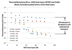
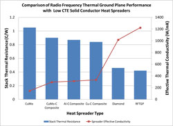
Ultimately, the value of a TGP is determined by its ability to provide higher performance at lower cost when compared to SoA and alternative emerging commercial solutions. To facilitate this comparison, our “Phase III” RFTGP design was compared head-to-head with solid conductors of equivalent size and CTE using the test facility described in [2]. The TGP provides substantial advantages relative to both SoA CuMo of identical CTE, with maximum benefit being obtained under boiling-dominated conditions (Figure 6). In the tested configuration, the TGP offers a peak effective isotropic thermal conductivity greater than 1200W/mK, which is superior to that of all known composites and comparable to mid-grade polycrystalline diamond (Figure 7), which also exhibits a significantly lower CTE. It achieves this performance using low cost materials and fabrication techniques, while also retaining key attributes required for use in precision electronics packaging applications.

Conclusions and Future Directions
Through the DARPA-supported Radio Frequency Thermal Ground Plane program, we have developed a cost-competitive CTE-matched vapor chamber technology that offers significant performance advantages relative to solid conductor alternatives. We have also demonstrated that CNT-functionalized Cu powder and Cu foam wick structures can provide higher levels of performance and reduce sensitivity to operating conditions (e.g., heat input, temperature). While additional work is needed to mature these novel materials, the combined work conducted in our TGP effort has firmly established their utility. We expect the TGP technology developed in this effort to have a significant impact on both defense and commercial electronics packaging technology.
Acknowledgement
The authors gratefully thank Dr. Thomas Kenny and Dr. Avram Bar-Cohen for their leadership and support on the Thermal Ground Plane program. This material is based upon work supported by the Defense Advanced Research Project Agency (DARPA) and Space and Naval Warfare Systems Center (SPAWARSYSCEN) San Diego, CA under Contract No. N66001-08-C-2011. The views expressed are those of the authors and do not reflect the official policy or position of the Department of Defense or the U.S. Government.

Bibliography
[1] Prasher, R. “A Simplified Conduction Based Modeling Scheme for Design Sensitivity Study of Thermal Solution Utilizing Heat Pipe and Vapor Chamber Technology,” ASME Journal of Electronics Packaging, 2003, v 125(3), 378-385.
[2] Altman, D., Wasniewski, J., North, M., Kim, S., & Fisher, T. “Development of Micro/Nano Engineered Wick-Based Passive Heat Spreaders,” Proceedings of the ASME 2011 Pacific Rim Technical Conference and Exhibition on Packaging and Integration of Electronic and Photonic Systems, MEMS and NEMS, IPACK2011-52122, July 6-8, 2011, Portland, Ore.
[3] Sauciuc, I., Chrysler, G., Mahajan, R., & Prasher, R. “Spreading in the heat sink base: Phase change systems or solid metals?” Thermal Challenges in Next Generation Electronic Systems, 2011, Rotterdam: Millpress, pp. 211-220.
[4] Weibel, J., Garimella, S., & North, M. “Characterization of evaporation and boiling from sintered powder wicks fed by capillary action,” International Journal of Heat and Mass Transfer, 2010, v 53, 4204-4215.
[5] Weibel, J., Kim, S., Fisher, T., & Garimella, S. “Characterization of Capillary-Fed Carbon Nanotube Vapor Chamber Wicks,” ASME Journal of Heat Transfer (In Review), 2011.
[6] Weibel, J., Garimella, S., Murthy, J., & Altman, D. “Design of Integrated Nanostructured Wicks for High Performance Vapor Chambers,” IEEE Transactions on Components, Packaging and Manufacturing Technology, 2011, v 1(6), pp. 859-867.
[7] Weibel, J., Kousalya, A., Fisher, T., & Garimella, S. “Characterization and nanostructured enhancement of boiling incipience in capillary-fed sintered powder wicks,” Proceedings of the IEEE Intersociety Conference on Thermal and Thermomechanical Phenomena in Electronic Systems (ITherm), 2012, (p. Abstract Accepted). San Diego: IEEE.
[8] Ujereh, S., Fisher, T., & Mudawar, I. “Effects of carbon nanotube arrays on nucleate pool boiling,” International Journal of Heat and Mass Transfer, 2007, v 50, pp. 4023-4028.
[9] Ranjan, R., Murthy, J., Garimella, S., & Altman, D. “An Experimentally Validated Model for Transport in Thin, High Conductivity, Low CTE Heat Spreaders,” Proceedings of the ASME 2011 Pacific Rim Technical Conference and Exhibition on Packaging and Integration of Electronic and Photonic Systems, MEMS and NEMS, IPACK2011-56039, 6-8, 2011, Portland, Oregon. Distribution Statement “A” (Approved for Public Release, Distribution Unlimited) [DISTAR Case 18510]


