Introduction
Developments in solid state lighting (SSL) in recent years have led to an extensive increase in the driving current of light emitting diodes (LEDs). Although corresponding increases in light output and efficiency has also been noted, current lighting design applications require the implementation of multiple diodes to allow its utilization in universal lighting applications. In contrast to incandescent lighting, where the majority of the heat generated from the filament is radiated directly to the ambient environment, 90% or more of the heat generated by the PN junction in a LED has to be dissipated through conduction [1]. Additional design considerations, such as cost, reliability, energy efficiency and noise, have limited the majority of cooling design options to natural convection via heat sinks as a primary mode of thermal dissipation. This provides extensive challenges with regard to thermal design, bearing in mind that the junction temperature directly influences the luminous output of the component, where elevated diode temperatures may cause color shift or adversely affect reliability [2-3]. In consideration of these challenges this paper examines the necessity and advantages of detailed system level numerical modeling to reduce experimental analysis and dynamically integrate the characteristics of the LED into the analysis process.
Design and Modelling Considerations
When considering the thermal design of a LED application, the thermal resistance of the constituent assembly, Rsystem, and the power it dissipates, Pd, becomes key parameters. Accurate knowledge of these values and how they interrelate not only allows the designer to calculate the junction temperature of the diode, described by Eq. 1, but also to determine its optimal lighting output.
Tjunction = Tambient + (Pd)( Rsystem) (1)

Commercial Computational Fluid Dynamics (CFD) software is extensively used to determine the pad-to-ambient thermal resistance. The problem with this approach is that the thermal load is unknown as it is an interdependent characteristic of the LED and the system. Compact models using a simplified parameter-based characterization are often used in an attempt to address this challenge [4]. The interdependency can best be explained by considering that the light produced by a high power LED is proportional to the driving current and temperature of the die. As the current increases the luminous flux will increase, but the resulting higher temperature will reduce the efficiency of the LED and may decrease the expected life of the component. Although the forward voltage of an LED is usually fixed by the binning, the effective forward voltages are related to the driving current and die temperature as it deviates from the nominal value. An increase in the driving current therefore alters the effective forward voltage that will change light produced by the LED and the heat dissipated by the component. The interdependency of these different aspects of a LED component is illustrated by the diagram in Fig 1. The complexity of analyzing the influence of these parameters on a design and determining its thermal resistance is increased even further when multiple LED’s are located on a single board or when transient applications, such as pulsed operations, are considered. A reliable LED model therefore has to account for all these parameters dynamically while calculating the system thermal resistance of the application. Furthermore, compact models are simply not good enough for this purpose. In addition, compact models have also shown extensive limitations when three-dimensional thermal effects are prevalent, as is the case with closely spaced LED arrays or with uneven thermal propagation through the board and heat sink base [5].
An alternative approach to system level design is the use of a detailed numerical representation of the LED, characterizing chip level features, coupled to a thermal resistance model which approximates the resistance between the pad and the ambient [6]. The complexity of modern heat sinks make it impossible to use simplified compact models to calculate the thermal resistance of applications and such models have very little practical value when considering natural convection cooling [7].
In order to address these issues this paper shows the results from a hybrid modeling approach that effectively combines conjugate thermal modeling of the system and detailed modeling of the LED characteristics to accurately represent the thermo-electrical interdependence of the constituent assembly. The thermal resistance can be obtained by either using a thermo-fluid network to model the fluid region coupled to a Finite Volume Method (FVM) representation of the solid or a detailed CFD analysis. The thermo-fluid network solution being significantly more efficient, whereas the detailed CFD analysis is more applicable to geometrically complex models.

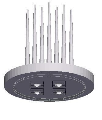
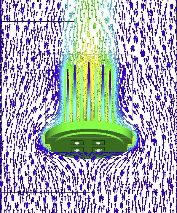
A typical thermal resistance model based on a thermo-fluid network is illustrated in Figure 2. The numerical efficiency of this modeling approach makes it very attractive to link a complete thermal model to an optimization algorithm in order to optimize geometrical effects for a specific application. When considering geometries where it is difficult to characterize the flow through a thermo-fluid network, the detailed CFD option can be used as illustrated in Figure 3.
In order to illustrate this modeling approach and the necessity of taking into account the system level thermo-electrical interdependence an optimization study will be considered. For this purpose the fluid-network based solver will be used in combination with the hybrid LED model and the Dynamic-Q optimization algorithm. The Dynamic-Q optimizer was chosen as it has previously shown to be efficient and very effective for the type of application under consideration and is integrated in the system-CFD solver implemented to perform the dynamically coupled numerical modeling [8-10]
LED Numerical Model
The detailed model of the LED assembly being considered is displayed in Figure 4. The assembly consists of six high-powered LED’s mounted onto an FR4 board with detailed vias. The LED-board assembly in part is mounted on an extruded aluminum heat sink with 10 fins. The heat sink base is oriented horizontally with the LED assembly facing downwards.
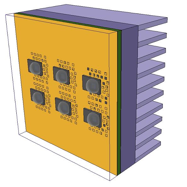
The internal architecture of the LED component model and its corresponding thermal properties and electric performance characteristics was obtained from the manufacturer and dynamically linked to the thermal solution to account for all LED interdependencies as outlined in Figure 1. The various elements which make up the LED component were modelled as three-dimensional conducting blocks. Approximately 4000 hexahedral cells were used to discretize the solid region and 900 thermo-fluid network elements to represent the fluid region. The detailed model was then linked to a commercial system-CFD solver [11].
Results and Discussion
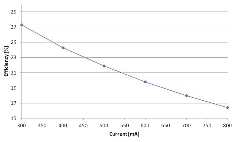
The numerically predicted LED operating efficiencies across the component driving current spectrum are displayed in Figure 5. The profile illustrates the scale of decrease in efficiency at higher load values, attributed to a reduction in the relative luminous output. This relation is specific to the thermal efficiency of the initial assembly design displayed in Figure 4.
The objective of the study is to minimize the heat sink mass of the initial design while remaining within the design restrictions of the LED array. The design variables that are considered are the heat sink base thickness, the number of fins of the heat sink and the fin height. The maximum die temperature is constrained to the maximum LED die temperature specified by the manufacturer. The variables and relating constraints are displayed in Table 1. The optimization algorithm implemented in the numerical model is based on the Dynamic-Q method [10].
|
|
Initial |
Constraint [min-max] |
|
Die Temperature |
95 °C |
95°C |
|
Fin Height |
15 mm |
5 mm – 20 mm |
|
Base Height |
5 mm |
3 mm – 7 mm |
|
Number of Fins |
10 |
4 – 15 |
Table 1. Initial design values and optimization constraints
The optimization study converged in seven optimization iterations. Each optimization iteration consists of solving a model for each of the three variables, then obtaining a new design from the optimizer and a fourth simulation to evaluate the design proposed by the optimization algorithm. By using the fluid-network based solver the optimization study was completed in 83 minutes on a laptop computer with a 2.5 Ghz Intel Core Duo 64 bit processor.
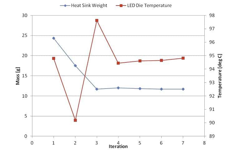
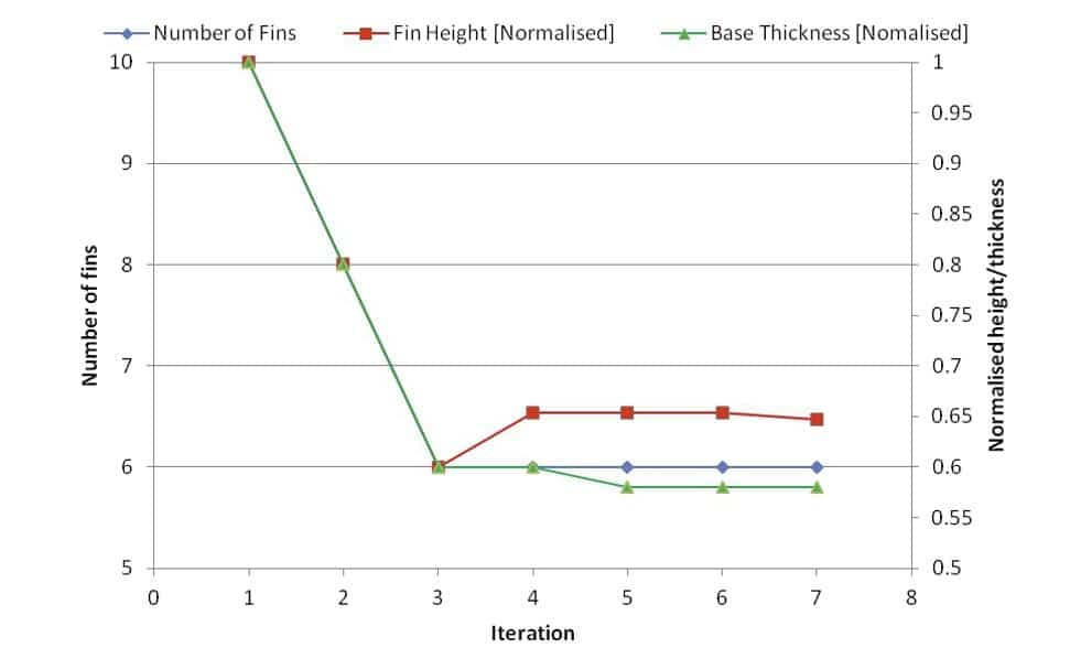
The decrease in heat sink weight and relating variation in die temperature is displayed in Figure 6. The changes of the three geometrical variables per iteration are displayed in Figure 7. The fin height and base thickness variables are normalized with respect to its initial size to facilitate comparison. During the initial optimization iteration a reduction in the die temperature is noted along with a decrease in the geometrical variables. This decline in die temperature can be attributed to an increase in the convective efficiency of the heat sink layout, primarily the reduction in the number of fins to aid buoyancy driven flow. Further reduction of the geometrical variables in the following iteration starts impeding the conductive efficiency of the heat sink. This can be noted by the drastic increase in die temperature and corrective increase in fin height applied by the optimizer in the following iterations. The final optimized results show a 60% decrease in the heat sink weight. More importantly, the study illustrates the interdependent complexity of design parameters which necessitates an integrated system level modeling approach and its advantages from a design point of view.
Conclusion
The paper highlights the challenges relating to the thermal design of LED lighting systems as well as the necessity of detailed system level modeling. Prominent issues relating to numerical modeling LED lighting systems are also addressed. This includes the limitation of compact resistor models and the necessity to consider the electric-thermal interdependence of the LED component and cooling system. In order to address these issues the paper described the implementation of a hybrid modeling approach which allows for detailed model of the LED component and conjugate heat transfer modeling of the entire design. A design optimization example was considered to further illustrate the effectiveness of this modeling approach.
References
1.) Petroski, J., 2004,“Spacing of high-brightness LEDs on metal substrate PCB’s for proper thermal performance. in Thermomechanical Phenomena in Electronic Systems”, Proceedings of the Intersociety Conference, Las Vegas, NV, United States: Institute of Electrical and Electronics Engineers Inc., Piscataway, United States.
2.) Chang. M-H., Das, D., Varde, P.V., Pecht, M., 2012, “Light emitting diodes reliability review”, Microelectronics Reliability, Volume 52, Issue 5, pp762-782.
3.) Bielecki, J. Jwania, A.S. El Khatib, F. Poorman, T. , 2007, “Thermal Considerations for LED Components in an Automotive Lamp”, Semiconductor Thermal Measurement and Management Symposium, 2007. Semi-Therm 2007, pp37-43, 10.1109/STHERM.2007.352403.
4.) Biber, C., 2008, “LED Light emission as a Function of Thermal Conditions”, Semiconductor Thermal Measurement and Management Symposium, 2008. Semi-Therm 2008, pp.180-184, 10.1109/STHERM.2008.4509387
5.) Christensen, A., Ha, M., Graham, S., 2009, “Thermal Management Methods for Compact High Powered LED Arrays”, Seventh International Conference on Solid State Lighting., San Diego, CA, USA.
6.) Ye, H., 2011, “Numerical modeling of thermal performance: Natural convection and Radiation of Solid State Lighting”, EuroSimE 12.
7.) Yu, E., Joshi, K.Y., 2000, “Natural Convection Air Cooling of Electronic Components in Partially Open Compact Horizontal Enclosures”, IEEE Transactions on Components and Packaging Technologies, vol. 23, pp 12-22.
8.) Craig, K.J., de Kock, D.J., Gauche, P, “Optimization of Heat Sink Mass using CFD and Mathematical Optimization”, ASME Journal of Electronic Packaging, Vol. 121, Nr. 3, 1999, pp. 143-147.
9.) Visser, J.A., de Kock, D.J., Conradie, F.D., 2000, “Minimisation of Heat Sink Mass Using Mathematical Optimisation” , Semiconductor Thermal Measurement and Management Symposium, 2000, Semi_Therm 2000, pp. 252-259, 10.1109/STHERM.2000.837091
10.) Snyman, J.A., Sander, N., Roux, W.J., 1994. “A Dynamic Penalty Function Method For The Solution of Structural Optimization Problems”, Applied Mathematical Modelling , Vol. 18, 1994, pp. 453-460.
11.) Qfin5 system-CFD/CFD solver, http://www.qfin.net/drupal/products
Gerard Scheepers is currently a technical services and consulting engineer at Qfinsoft Technology Inc, specializing in the application of system-CFD modeling techniques for electronics cooling applications. He is currently pursuing a Ph.D. degree in Mechanical Engineering. His research topic considers the development of an automated decomposition algorithm for the construction of thermo-fluid network elements through an arbitrary geometry.
Jan Visser is the President and CEO of Qfinsoft Technology Inc. He received his PhD from the University of Pretoria in 1989. His current research interests include the dynamic coupling of temperature dependent electronic components like LEDs to numerical simulation software to accurately predict the performance of the devices at system level.


