Bruce Guenin, Assoc. Editor, Electronics Cooling
View Part 1 here.
Introduction
This two-part column was motivated by concerns regarding the important role of organic materials in electronic systems and their accompanying vulnerabilities due to moisture diffusion. The methods described herein are intended to provide an efficient means of predicting the rate of moisture diffusion under a variety of conditions in order to better manage the associated risks.
Part 1 established the basic validity of the methodology and demonstrated its use in modeling 1-D (one-dimensional) diffusion flow geometries[1]. Part 2 continues the development of these methods and applies them to a variety of situations of practical importance.


Calculation Method for 2-D Diffusion Geometries
As demonstrated in Part 1, the use of a multi-stage RC (resistor-capacitor) network, solved using a numerical method, can be extended beyond its original scope involving thermal transient modeling to the prediction of moisture diffusion. It can be adapted to various geometries by using the appropriate analytical formulas for calculating the particular values of R and C. The execution of the numerical method is relatively independent of these geometrical details.
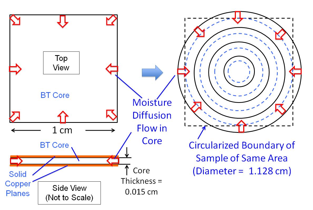
Figure 1 depicts the geometry assumed in the calculation, that is representative of the design of organic laminates used in package substrates and PCBs (printed circuit boards). It represents a single dielectric core region in a muli-layer package substrate. The core material is the same as that in Part 1, namely, BT ((bismaleimide triazine). The BT is assumed to be 0.015 cm thick and is 1 cm square. It is assumed to be sandwiched between two continuous copper planes. The presence of the copper is not explicitly accounted for in the model. Their effect, as far as the model is concerned, is to prevent any diffusion of moisture into the BT from its top and bottom surfaces. Moisture can only diffuse into the core by way of the exposed edge. Note that this is a rather constraining condition. To the extent that the metal planes prevent the diffusion of moisture from one core to another, it is only necessary to model a single core to capture the physics of the diffusion process.
However, in the real world, life is not quite this simple. Typically, in laminated organic package substrates and PCBs, there are perforations in the metal planes as required by the fabrication process or resulting from via or trace routing in the laminate. These perforations would serve to provide additional paths for moisture to diffuse into the interior regions of the laminate. Hence, the time for moisture diffusion in actual components would tend to be less than that predicted here. However, the simple construction assumed here will enable us to more efficiently explore the basic physical effects involved with the exchange of moisture between an organic substrate and the ambient air and simultaneous diffusion within the component.

Before the numerical method can be applied, it is necessary to subdivide the sample into several regions, each of which must be represented by a separate value of R and C in the RC circuit. There is no standard way to do this. However, the method used in Part 1 for a 1-D flow in a slab-shaped component can be adapted to the 2-D situation as follows:
• Circularize the square by transforming it into a disk having an equal area. This has been shown to be a reasonable approximation for radial heat flow in a square geometry[2].
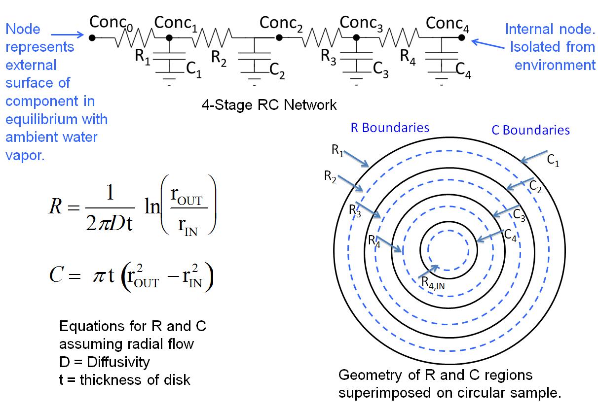
• To create the capacitor volumes, divide the disk into 4 annular regions for which rOUT – rIN = rDISK/4, where rOUT and rIN are the outer and inner radii of a given annulus and rDISK is the radius of the disk. This is depicted by the array of concentric solid-line circles in Figure 1.
• The resistor geometries span two adjacent annuli and terminate at the bisecting radius of each. [The bisecting radius divides each capacitor annulus into two equal areas.] This is depicted by the array of concentric dotted-line circles in Figure 1.
• The C and R values can be calculated using the particular values of rOUT and rIN of the appropriate annuli and the appropriate formula in Figure 1.
Table 1 lists the inner and outer radii for each C and R region, and the resultant C and R values. The R calculations assume three different diffusion coefficients, one for each of the three BT temperatures assumed in the case studies to follow.
Visually, the most prominent feature of the 4-stage RC circuit is the ladder arrangement of the resistor and capacitor symbols. From a physical perspective, the topology of this network and the particular R and C values will determine how rapidly moisture will be transported through the structure. However, the value of Conc0 , the moisture concentration at the outer skin of the BT, is important in providing the potential difference to drive the diffusive flow of moisture either into or out of the BT. The value of Conc0 is, in turn, determined entirely by the local RH at the exposed surface of the BT and by its local temperature.
Hence, in order to accurately predict the instantaneous diffusion rate within the BT, it is necessary to determine:
• The diffusion coefficient — it is determined only by the choice of organic material and its temperature.
• Local RH at the exposed surface of the organic material — determined by the ambient temperature and RH and the local temperature of the material.
• Equilibrium value of Conc0 — determined by the local temperature and local RH and the choice of organic material.
The following sections provide procedures for calculating each of these properties and the relevant environmental conditions.

Diffusion Coefficient
In Part 1, a method of calculating D for BT was described using Eqn. 3 (in Part 1), and assuming an activation energy for moisture diffusion of 0.48 eV. Table 2 provides calculated values of D at temperatures of interest. Since D is an exponential function of temperature, its value changes significantly with changes in temperature.
Relative Humidity at Interface with the Sample
The value of RH at the interface with the polymer component plays a significant role in the ultimate moisture concentration in the sample. It is critically dependent on the ambient temperature. In situations in which the substrate temperature differs from that of the ambient, then this difference must be taken into account.
The following equation, which provides the relationship between the partial pressure of water in the atmosphere, at saturation, as a function of temperature, can be used as the basis of all the required relative humidity calculations.
(1)
where PWater, Sat is the partial pressure of water in units of Pa and T is the absolute temperature, in units of K [3]. At a given value of RH, the partial pressure of water is simply equal to
(2)


Moisture Concentration at the Sample Surface
The relationship between the saturated moisture concentration and ambient temperature and RH for BT samples in equilibrium with the ambient has been quantified though weight measurements on saturated samples [4]. Figure 3 shows the result of applying a regression analysis to the raw data from the reference and provides a means of estimating values of moisture concentration at values of temperature and RH other than those measured. Furthermore, a power law regression (not shown on the graph) was generated for each trendline and was used to estimate values for RH between 0 and 40%.
Moisture Diffusion Calculations for 6 Case Studies
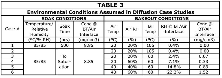
A total of 6 case studies were performed. They are listed in Table 3. In all cases there was a soak process under 85˚C/85%RH conditions. For Case 1 the soak process lasted for 500 hours, and was simulated explicitly. For all other cases, they were assumed to proceed to saturation. They were not explicitly simulated. Their effect was represented by assigning a constant value of concentration (equal to 8.85 mg/cm3) to all of the capacitors as an initial condition in the bakeout simulation.
Cases 1 and 2 are similar to the one analyzed in Part 1. The simulation results for these cases are shown in Figure 4. In this Figure, the top row of graphs plot the value of moisture concentration calculated for each of the capacitors at various values of elapsed time. For a given time, the radius value associated with each data point represents that of the bisecting radius of each capacitor.
The middle row of graphs plot the concentration calculated for each capacitor versus time. C1 is associated with the outermost annulus. As such, its concentration is the fastest to rise during soaking and likewise to fall during bakeout.
The bottom row of graphs plots the total mass of absorbed moisture vs time. It is calculated using Eqn. 3, below.
(3)
(Note that the equivalent equation in Part 1 (Eqn. 4) had a prefactor equal to 2 to compensate for the half symmetry of the 1-D model.)
The results for the soak process in Case 1 are worth noting. In spite of the 500 hr duration, the moisture concentration at the center of the sample reached only about half of its saturation value. This is simply due to the rather large radius on the modeled sample, equal to 0.56 mm. By comparison, in Part 1, the diffusion length between the mid-plane and the exterior surface of the sample was 0.012 mm. Here, full saturation was achieved in only about 4 hours.
The bakeout process for these two cases assumes the use of an oven set to a temperature of 105˚C. Since the oven is assumed to be open to the atmosphere, in the vicinity of the BT, a very low RH value of 0.4% is calculated. At this high temperature, the diffusion coefficient is high enough that the bakeout is complete at approximately 650 hrs. This was nearly independent of the initial moisture content of the BT at the start of bakeout.
The bakeout process for Cases 3-6 are more representative of conditions in application environments. In all four cases, the temperature of the BT was assumed to be 60˚C, which was higher than the ambient temperature in each case.
Cases 3 and 4 assume an ambient temperature of 20˚C, at RH values of 20% and 40%, respectively. These would be considered rather mild application environments and would be representative of ASHRAE data center guidelines of today. These results are displayed in Figure 5. The time required for the moisture content to reach a steady minimum is nearly 5000 hours. As mentioned, this is probably a conservative estimate. However, it is indicative of a much slower drying process than in a dedicated bakeout oven. One notes, also, the beginning of a trend in that the residual moisture level in the BT is greater than the near zero value obtained in the bakeout oven. These residual moisture concentration levels were calculated at 0.07 and 0.3 mg/cm3, respectively.
There is a trend among data centers to push ambient temperature and RH values to higher levels in the interest of improving data center cooling efficiency. ASHRAE has been supportive of this trend by relaxing temperature and humidity guidelines and allowing temperatures in the 40 to 45˚C range, with appropriate controls on humidity [5]. Cases 5 and 6 assume an ambient temperature of 40˚C and RH levels of 40 and 60%, respectively. The results in Figure 5 indicate a similar time for the residual moisture to reach a stable value. This should not be a surprise, since this is largely the result of the BT temperature, since this determines the diffusion coefficient. However, the residual concentration values of 0.8 and 1.5 mg/cm3 are significantly higher than those associated with the 20˚C ambient.

Conclusions
Computationally efficient methods have been demonstrated that are useful in calculating moisture diffusion rates for simple geometries over a wide range of ambient conditions of temperature and humidity.
The use of ambient air with elevated temperature and humidity levels for cooling electronic components containing organic materials has been shown to promote a higher concentration of residual moisture in these materials. It behooves the industry to not only quantify moisture levels in organic materials more effectively, but also to better understand the impact of increased moisture levels on the reliability and electrical performance of these materials.
References
1. B. Guenin, “Application of Transient Thermal Methods to Moisture Diffusion Calculations, Part1,” ElectronicsCooling, Vol. 18, No. 4 (2012).
2. B. Guenin, “Heat Spreading Calculations Using Thermal Circuit Elements,” ElectronicsCooling, Vol. 16, No. 3 (2010).
3. Engineering Toolbook webpage, http://www.engineeringtoolbox.com/water-vapor-saturation-pressure-air-d_689.htm
4. M. Pecht, H. Ardebili, A. Shukla, J. Hagge, and D. Jennings, “Moisture Ingress Into Organic Laminates,” IEEE Trans. Comp. Pack. Tech., Vol. 22, No. 1, (1999) pp. 104-110.
5. R. Schmidt, “A History of ASHRAE Technical Committee TC9.9 and its Impact on Data Center Design and Operation,” ElectronicsCooling, Vol. 18, No. 4 (2012).


