Two different package styles, two very different thermal responses when a extruded plate fin heatsink is placed on each. At the very least a FloTHERM simulation can be used to observe the thermal behaviour of a product concept, beyond that it can be used to understand *why* the thermal behaviour is what it is.
In Part 1 we saw that the BGA type package benefited from an 81% drop of junction temperature rise over ambient whilst the TO package only dropped by 27%. To understand why such a difference let’s consider the heat flow within the package prior to a heatsink being deployed.

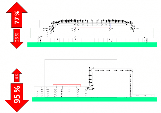
Thermal design engineers often characterise heat flow in terms of heat flow budgets. That is a more macro description of the dominant heat flow paths, what % of the total heat flows where. Such budgeting is also sometimes used to summarise the proportion of heat that passes through a surface by convection, conduction and radiation. In this case, looking at the budget for the die, 77% of the heat flows directly up through the die to pass near the top surface of the package, due in no small part to the nice metal spreader and slug designed specifically for that purpose. This is before a heatsink is placed on top, mind.
For the TO package 95% of the heat prefers to pass directly to the PCB. Again not surprising considering that was the design intent. As a piece of heat (eh?), metal is as attractive to you as would be the illicit love child of Jessica Alba+Mena Suvari or George Clooney+Leonardo DiCaprio [select as is appropriate to your leaning, or gender, or both]. To a piece of heat, low thermal conductivity epoxy based encapsulant is more like being forced to .. (I’ll stop there).
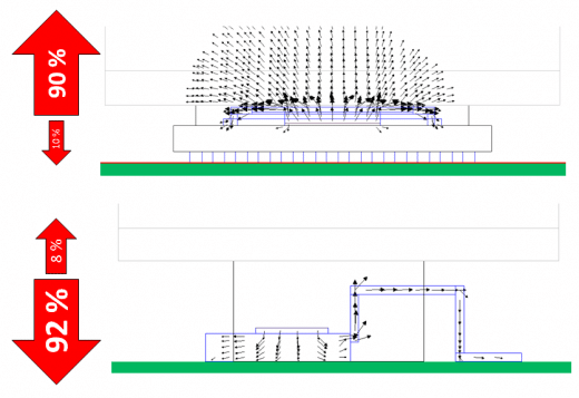
So, what happens to the budget when a nice fat metal heatsink is plonked on top of both packages?:
The 77% of the heat that was going up before the heatsink was placed on top has now been upped to 90%. The heatsink provides a welcome helping hand to a whole bunch of heat that was already waiting on the pier for the boat (so to speak, sorry, getting rather carried away with my similies). Thus the substantial reduction in junction temperature rise. The more readily the heat can leave the lower the temperature rise that backs up behind it.
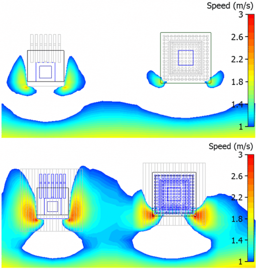
For the TO package there’s only a very minor 3% shift in the budget. So why the 27% reduction in junction temperature rise? The answer to that lies not in the conductive effects of the heatsink (there are little) but in the effect the heatsink has on the air flow disruption that it causes.

[For those thermal experts out there; this is a fixed flow type environment with limited allowance of by-pass so there’s no coupling in this example between pressure loss, flow rate and thermal performance as you’d find in reality]
Any good thermal engineer wouldn’t be happy with only a 27% drop in dT after having considered spending so much on a heatsink. There are better ways to assure an even bigger dT drop for the TO type package. More on that in Part 3.
15th May 2013, Ross-on-Wye


