This article presents an analysis methodology that can be used to calculate the thermal resistance of a vertical downward facing vapor condenser plate-fin heat sink, i.e. a heat sink in which the plate-fins extend downward from a horizontal base into a coolant vapor region and whose function it is to condense this vapor into liquid condensate. Such heat sinks are used in cooling systems where the heat rejection from the source is carried out via a coolant boiling process and this heat is then rejected to an ambient fluid (air or liquid) using a vapor condensation process.
Figure 1 displays an elevation view of a dielectric coolant immersion cooled electronics module in which pool boiling from a “boiling” heat sink attached to the back side of a microprocessor chip is the primary heat dissipation mechanism from the device. The coolant has a boiling point that is much lower than the target surface temperature of the electronic device. For example, the coolant could be HFE7000 [1] which boils at approximately 35oC at atmospheric pressure. If the target boiling fin surface is 60oC, then, this allows for as much as 25oC of superheat (temperature excess) between the fin and the local liquid coolant. The magnitude of boiling heat transfer coefficient on the fin surface, and thus the thermal performance of the heat sink, is dependent on this superheat. A methodology on how to calculate the thermal resistance of such a boiling heat sink was provided by Simons [2]. Applications for pool boiling based cooling of IT equipment have been discussed further in Tuma [3].

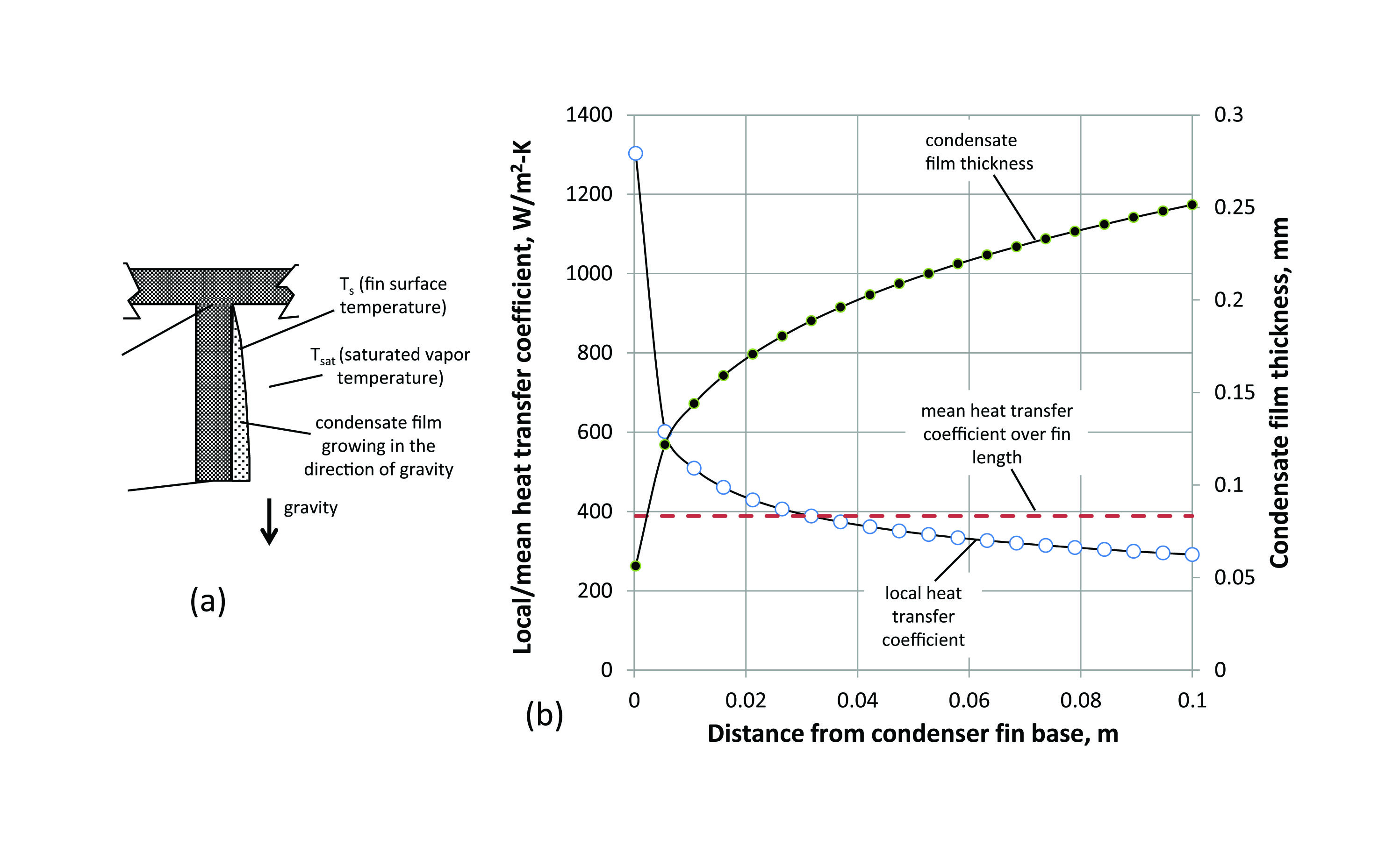
The vapor generated from the pool boiling phenomenon rises to the top of the immersion cooled module where it comes in contact with the fins of a condenser heat sink. The condenser heat sink is attached via a thermal interface material to a liquid cooled cold plate with liquid flow at a temperature lower than the boiling point of the encapsulated vapor. The cold plate serves to transfer the module heat load from the immersion coolant to the liquid loop circulating at the system level. The vapor in contact with cool condenser fins condenses into a liquid film which flows downwards along the length of the fin. Thus, as depicted in Figure 2(a), the condensate film grows thicker along the length of the vertical surface (i.e. the fin), in the downward direction against gravity, and at the end of the fin, the condensate droplets that form, fall back into the liquid pool that submerges the electronics chip. Also depicted in Figure 1 is a non-condensable gas layer, which is usually air that was dissolved in the coolant. The impact of this thin layer on the thermal performance of the heat sink will be ignored in this analysis.

Table 1: Input parameters for calculations shown in Figure 2(b).
| Parameter | Symbol | Units | Value |
| Length of vertical surface (fin) | L | m | 0.1 |
| Temperature of vertical surface (fin) | Ts | oC | 25 |
| Coolant type |
— |
— |
HFE7000 [2] |
| Temperature of saturated vapor | Tsat | oC | 35.3 |
| Liquid density of coolant* | rl | kg/m3 | 1399.4 |
| Vapor density of coolant** | rg | kg/m3 | 8.34 |
| Coolant liquid specific heat* | Cp | J/kg/K | 1076 |
| Latent heat of vaporization | hl | J/kg | 142000 |
| Coolant liquid dynamic viscosity* | ml | kg/m-s | 0.00039961 |
| Coolant liquid thermal conductivity* | kl | W/m-K | 0.073 |
Note: Coolant properties evaluated at mean condensate film (*) or saturated coolant (**) temperature.
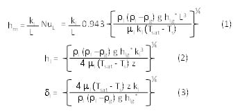
Figure 2(b) shows the variation of the local condensation heat transfer coefficient at increasing distance from the base of the condenser fin for the conditions described in Table 1. Several of the thermodynamic values were calculated using commercial software [4] or from coolant literature [1]. The values for the local and mean heat transfer coefficient and the local condensate film thickness are calculated using the Nusselt equations for laminar flow of condensate over a vertical flat plate that has been provided by Rohsenow [5], and given by,
where, NuL is the Nusselt number average over the length L, z (m) is the distance from the fin base in the downward vertical direction, g is gravitational acceleration (9.8 m/s2), and hfg* is a effective latent heat of evaporation that is given by,
Observing Figure 2(b), one can see that as the condensate film gets thicker the local heat transfer coefficient drops significantly, because the heat has to be conducted through the liquid film thickness. It should be noted that the equations (1)-(4) are for laminar condensate flow. After a certain fin height though, the flow could turn to laminar wavy or turbulent yielding higher heat transfer coefficients. This aspect is beyond the scope of this article. Interestingly, the absolute values for the film thickness are quite small even for long fins (e.g. 0.1 m) as shown in Figure 2(b). So, it would not be difficult to design a heat sink that has a wide enough gap between the fins to accommodate the film thickness growth.
The analysis in Figure 2(b) does not take into account any temperature drop along the length of the fin, i.e. it does not capture fin efficiency, which one would expect, would be an important factor given that the heat transfer coefficients are so high (Figure 2(b)) and that the temperature difference between the surface and the vapor is itself an parameter used to calculate the heat transfer coefficient (equation (1)). Thus, accounting for the fin efficiency effect in equation (1), et,
where hfin is the fin efficiency, which can be calculated using,
hfin = tanh(mL)/mL (6)
where m is a fin parameter and given by,
m = [hmP/kA]0.5 (7)
where P, is the fin perimeter, k is the fin material thermal conductivity, and A is cross-sectional area of the fin. For a fin whose width is D and thickness is t, the perimeter P is equal to 2(D+t) and the cross-sectional area is equal to Dt. For a very thin fin, the P can be approximated to 2D which allows the m to be approximated to [2hm,fin/kt]0.5. It should be noted that equation(7) is based on several assumptions including an insulated fin tip, a constant heat transfer coefficient, and quassi 1-D heat flow through the fin.
Using the mean fin heat transfer calculated using equation (5), the condensation heat sink heat dissipation rate can be calculated using,
Qfins =N hfin hm,fin A (Tsat – Ts) (8)
where N is the number of fins. N can be approximated to be W/(s+t), where W is the width of the heat sink, s is the fin to fin gap, t is the fin thickness, and the number of fins and gaps are equal or there are a large number of fins. If there are N fins and (N-1) gaps, i.e. both ends of the heat sink has fins, then W = Nt + (N-1)s. If there are N fins and (N+1) gaps, i.e. both ends of the heat sink has gaps, then W = Nt + (N+1)s.
In equation (8), A is the surface area of the fin that is given by,
A = 2L (D+t) (9)
Equations (8) and (9) ignore the contribution of the exposed base are of the heat sink that is in contact with the coolant vapor. This is valid for long fins where the fin area is much larger than the exposed base area.
The thermal resistance of the condenser fins can then be calculated using,
Rfins = 1 / N hfin hm,fin A (10)
The total thermal resistance of the condenser is thus the sum of the base and fins thermal resistance, and given by,
Rcondenser = Rfins + tbase/(kbaseWD) [11]
where tbase is the thickness of the condenser base.
Thus, the total heat dissipation rate of the condenser heat sink can be calculated using,
Qcondenser = Rcondenser [Tsat – Tbase] [12]
where Tbase is the base temperature of the condenser that interfaces with the liquid cooled cold plate.
Figure 3 shows predictions for calculating the heat dissipation from a vapor condenser of different sizes and made from three materials using equations (5)-(12). The geometry and material assumptions utilized for the calculations are provided in Table 2.
Table 2: Parameters for condenser heat sink analyses displayed in Figure 3.
| Parameter | Symbol | Units | Value |
| Length of vertical fin | L | m | 0.005 – 0.1 |
| Depth of the fin (along the fin) | D | m | 0.1 |
| Width of the condenser heat sink | W | m | 0.1 |
| Thickness of heat sink base | tbase | m | 0.0025 |
| Fin thickness | t | m | 0.005 |
| Fin gap | s | m | 0.0056 |
| Number of fins | N | 10 | |
| Fin thermal conductivity | k | W/m-K | 156, 200, 400 |
| Saturated vapor temperature | Tsat | oC | 35.3 |
| Heat sink base temperature | Tbase | oC | 25.3 |

As may be seen from Figure 3, the vapor condenser heat sink cooling capability increases sharply with fin length for short fins, but plateaus after the fins are approximately 0.05m-long. For really short fins, e.g. 0.005 m, the fin efficiency is significantly high (> 0.95), and there is minimal difference between different materials such as magnesium, aluminum, and copper which have thermal conductivities in the 150-400 W/m-K range. For the calculations presented herein, the assumption that the fin base temperature is approximately equal to the base of the condenser heat sink has been made. This is valid for a thin condenser base. It should also be highlighted than the fin efficiency equation cited in equations (6)-(7) is applicable only for long thin fins. Consequently, while results are presented herein for short fins (5-30mm), the author cautions the user if they use data for short fin lengths (e.g. < 30 mm), as the temperature distribution in the fin might be significantly 2-D and thus the fin efficiency equation used may not be applicable. Also, it should be further noted that the fin spacing assumed must be greater than twice the condensate film thickness for the analyses presented herein to be valid, i.e. the film heat transfer coefficient is considered to be independent of fin spacing. For example, Figure 2 shows a maximum condensate film thickness of 0.25mm; thus the fin spacing must be greater than 0.5 mm when applying these equations for the conditions listed in Table 1. The calculation performed using equations (5)-(12) required the solutions of several simultaneous equations with several unknown variables using a commercial software [4].
References
[1] 3M Novec Engineered Fluid HFE-7000,
http://solutions.3m.com/wps/portal/3M/en_US/GovernmentSolutions/Home/ProductInformation/Online_Catalog/?PC_7_RJH9U5230GO250IANS2O1A3I71000000_nid=J8X6XQS1WRbe8ML40JJLMNgl, last accessed August 6, 2013
[2] R. Simons, 2009, “A Simple Method to Estimate Boiling Heat Sink Performance”, ElectronicsCooling, https://electronics-cooling.com/2009/02/a-simple-method-to-estimate-boiling-heat-sink-performance/
[3] P. Tuma, 2010, “Open Bath Immersion Cooling In Data Centers: A New Twist On An Old Idea”, ElectronicsCooling, https://electronics-cooling.com/2010/12/open-bath-immersion-cooling-in-data-centers-a-new-twist-on-an-old-idea/
[4] Engineering Equation Solver, www.fchart.com
[5] W. Rohsenow, and H. Choi, 1961, “Heat, Mass, and Momentum Transfer”, Prentice Hall, NJ, USA.


