András Poppe, Ph.D.; Mentor Graphics MAD MicReD Unit
The electrical, thermal and optical parameters determining light emitting didoes (LEDs) operation are in a strong, mutual dependence; without knowledge about the parameters in one of these domains the other characteristics cannot be measured correctly. The reliability, useful operating life time and luminous flux are determined by the junction temperature of the LED device. This temperature is directly proportional to the total junction-to-ambient thermal resistance of the heat-flow path of the LED application. A dominant component of this overall thermal resistance is the junction-to-case thermal resistance of the LED package which is oneof the key data sheet entries among the electrical and light output properties of the device. Unfortunately, until recently, there has been no widely accepted standard or recommendation regarding the correct measurement of this thermal resistance. The article describes the most recent LED thermal testing standards published by JEDEC in 2012 together with the new transient method for the measurement of the junction-to-case thermal resistance of power semiconductor device packages with an exposed cooling surface – aimed at the correct measurement of LEDs’ thermal metrics for publication in a data sheet.
INTRODUCTION
Standardization is a wide ranging topic for which one can discuss extensively on product performance and testing standards. Until recently, standardization for LED products was lacking in comparison with those for classical light sources. For example, referring to “100W/230V E27/Par38 lamp” meant the same incandescent, directional light source everywhere in the world, regardless of its manufacturer.
Despite standardized nomenclature regarding LEDs aimed at solid-state lighting applications [1], there is currently no official classification. LEDs can be classified by color, outline or by luminous intensity (general, high brightness, ultra high brightness). The rapid evolution of power LEDs in terms of different forms and flavors of packages impedes the definition of such component-level product standards. On the other hand, for assembly or module level units there have been attempts to develop interchangeable products. One representative product concept is, for example, GE’s Infusion series of LED modules. A similar, but generalized concept is promoted by the Zhaga consortium [2] formed by several hundred LED vendors and luminaire manufacturers. The consortium aims to resolve the problem of LED product interchangeability by defining different LED modules and LED light engines each with clear definitions regarding their so-called electrical, mechanical and thermal interfaces. The goal is to enable interchangeability of LED light sources made by different manufacturers. Book1 of Zhaga specifications, already available to the general public, describes the generic concepts, terms and definitions used by Zhaga, including thermal-related topics. Additional Zhaga specification books define particular interface details for different LED light engine types. So far Book 2 and Book 3 are available to the general public. Zhaga plans to publish further (Books 4 to 8) outside the consortium at a later time. Though Zhaga have their own test specifications, none of the Zhaga books defines how to test thermal or thermal related properties of LEDs or LED products. The main focus is on determining the compliance to the different interface specs (electrical, mechanical, photometric, thermal) of Zhaga.

Thermal issues of LEDs are of paramount importance due to two reasons. On one hand, long-term reliability strongly depends on the operating junction temperature of the LEDs as most of the failure mechanisms leading to light output degradation are thermally assisted. Statistically seen this means that the so called “lumen maintenance” (precisely: long term maintenance of the emitted total luminous flux) of LED components is determined by the junction temperature: at higher junction temperature light output degradation happens more quickly. This is nicely illustrated by the so called Bxx-Lyy diagrams such as the B50-L70 plots usual in product data sheets. Such plots (see e.g. Figure 2 in [3]) present the expected life time of a power LED product as function of its junction temperature and forward current in terms of drop of its luminous flux to the 70% of the initial value (L70) in case of 50% of the investigated LED population (B50) – this being defined as failure condition (B50-L70).
On the other hand, the light output characteristics of LEDs strongly depend on the operating conditions. The forward current applied to an LED is the key variable; the higher the supplied current, the more light that is generated by the device. But the LED’s light output drops when its junction temperature increases, even when the device is driven by a constant current source. This illustrated in Figure 1. Both the intensity and the color output of an LED suffer when heat builds up. In Figure 1, the shift in the peak wavelength is evidence of a color change in the emitted light. Clearly this is not acceptable within an array of LEDs expected to produce homogeneous color over a large area, or when color stability is a strict requirement like in case of traffic lights.
Thermal testing of LED components, or small LED assemblies, falls within the general category of thermal testing of packaged semiconductor devices – therefore the JC15 committee of JEDEC (Joint Electron Devices Engineering Council), dealing with on thermal characterization of packaged semiconductor devices initiated a series of white papers on the need for LED thermal testing standards (see e.g. [3]).
Based on the above discussions, the objective of this article is to provide an overview on results of the last five years’ work
of the JC15 committee by introducing the major concepts
of LED thermal testing and providing a brief description of
JEDEC’s published standards of thermal testing of LED components
[4], [5] , [6], [7] (LED packages or LED assemblies).
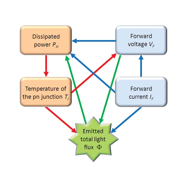
The JEDEC JC15 committee also deals with (compact) thermal modeling of semiconductor device packages aimed at board and system level thermal simulations. Such models are common for electrical components but due to the complex behavior of LEDs (see Figure 2) there are no standardized LED compact models yet which cover this multi-domain operation. This field is still the subject of additional research and future standardization. For an overview of the current state of the art on LED compact modeling the interested reader is advised to refer to the relevant section of a recent book on thermal management of LED applications [8].
HOW TO MEASURE THE REAL THERMAL IMPEDANCE AND THERMAL RESISTANCE OF LED PACKAGES?
The New JEDEC Test Procedure for Obtaining Junction-to-Case Thermal Resistance of Power Semiconductor Device Packages
From the thermal point of view packaged LEDs are similar to any other power semiconductor device for which the most important thermal metric is their junction-to-case thermal resistance. For the accurate and repeatable measurement of this metric, the JEDEC JC15 committee has developed the new JESD51-14 testing standard [9] based on the so called transient dual interface method. This method is characterized as follows:
During the measurement it is assumed that there is a single heat conduction path from the junction (location of heating) towards the ambient through an exposed cooling surface of the package. This surface is called the package ‘case’. A further assumption is that such packages are designed to be heat-sunk during normal operation. Thus, during a JESD 51-14 compliant RthJC measurement the device under test needs to be attached to a cold plate. According to this standard the junction temperature cooling transients of the device need to be recorded twice, using the JESD 51-1 electrical test method [10], with two different qualities of the thermal interface between the package ‘case’ surface and the cold plate. In one measurement good thermal contact between the package ‘case’ and the cold plate need to be established (typically by applying a thermal interface material between the mating surfaces). This is also known as ‘wet’ condition as using a simple silicon oil wetting the interface is sufficient. In the other measurement poor thermal contact between the package and the test environment is required; that is no thermal interface material shall be used during this measurement. This condition is also known as ‘dry’ condition as no wetting material such ase silicon oil or thermal grease is used.
The effect of these two different qualities of the ‘case’ and ‘cold plate’ thermal interface on the two measured thermal impedance curves is that at a characteristic time the curves start diverging. The Rth value corresponding to this divergence point is the transient junction-to-case thermal resistance. The JESD 51-14 standard provides two methods to determine the ‘exact’ value of the transient RthJC value in a repeatable and reproducible way. One method is based on the difference between the structure functions2.
The divergence point appearing in the structure function plots showing the results of the two measurements (with TIM and with no TIM) gives the exact value of the RthJC junctionto- case thermal resistance of the package. According to the JESD 51-14 standard if the difference between the structure functions is greater than a pre-defined mismatch value, the divergence point is found. (The second method of finding the divergence point of the two measured thermal impedances defined in the standard is based on the difference of the first derivatives of these impedance curves – the divergence point and the corresponding RthJC value is found in a similar way as in case of the structure function based method.)
More details of the test method of the JESD 51-14 are given by Schweitzer e.g. in his paper published earlier in this magazine [11]. Müller et al [12] has published the first report on using this test method for the measurement of LEDs.
Measurement of the Real Thermal Resistance/Thermal Impedance of LEDs
A semiconductor device package is typically characterized
by a thermal resistance value specific for a given reference
environment. According to the classical, almost-two-decadesold
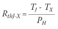
JESD 51-1 standard [10] the definition of the RthJ-X junction-to-reference environment X thermal resistance is:
where TJ denotes the junction temperature, TX is the temperature of the reference environment X, PH is the power dissipated at the the junction, i.e. the heating power. The RthJ-X junction-to-case thermal resistance discussed in the previous section is such a characteristic thermal metric.
In case of a silicon diode the heating power is the product of the voltage drop across the diode and the current flowing through the pn-junction. Considering the high energy conversion efficiency of today’s power LEDs (in case of high-end products close to 50 percent), during the calculation of the heating power one needs to consider the emitted optical power of the LED, the so called total radiant flux as well:
(2) PH = IF x VF – Фe
where IF and VF denote the LED’s forward current and forward voltage respectively, and Φe is the power of the emitted light, the radiant flux (also known as optical power and often denoted by Popt). The accurate measurement of the total radiant flux is very important especially since it strongly depends on the junction temperature and on the LED’s forward current (see Figure 2).
Thus, if the heating power is calculated according to Equation (2) during the JEDEC JESD 51-14 compliant transient junction-to-case thermal resistance measurements, the identified RthJC value will be the real, physical thermal resistance of the LED package; so this value (or the approximate RC Cauer-type ladder model with a total cumulative thermal resistance equal to this value) can be used for compact thermal modeling of the LED package. Regarding the evolving topic of LED compact modeling the reader is advised to refer to section 6.5.2. of chapter 6 in [8].
When identifying the thermal resistance according to Equation (1) the junction temperature is measured indirectly taking advantage of the fact that in case of forced, constant forward current the forward voltage of any pn-junction almost linearly depends on the junction temperature. This is called the electrical test method; most commercial test equipment are based on this principle. The temperature dependence of the forward voltage is identified with the so called K-factor calibration. According to the classical thermal testing standards the TX reference temperature also needs to be measured – this is typically done by using a thermocouple. The thermocouple also has to be calibrated. Thus, a disadvantage of the thermal resistance measurements based on Equation (1) is that two kinds of temperature sensors have to be calibrated: both the pn-junction and the thermocouple. From Equation (1) the junction temperature for two different values of the heating power (see also Figure 3b) can be expressed as:
(3a) TJ1 = RthJ-X x PH1 + Tx
TJ2 = RthJ-X x PH2 + Tx
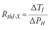
Subtracting Equation 3b from Equation 3a, the TX reference temperature
cancels out: ΔTJ = RthJ-x – ΔPH, thus
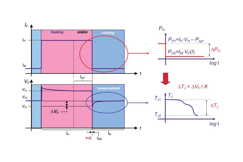
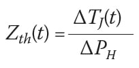
where ΔTJ = TJ1 – TJ2 and ΔPH = PH1 – PH2, as illustrated in Figure 3b. This can be interpreted as follows. First a large IH heating current (nowadays in the range of 350 mA to 1500 mA) is forced to the pn-junction of the LED. When at this current the junction temperature of the LED stabilizes (i.e. the forward voltage does not change any longer) one can measure the light output properties of the LED, including the Φe = Popt total radiant flux (emitted optical power) This measurement can be realized in an integrating sphere, following the recommendations of the CIE 127-2007 standard [13]. Knowing the forward current (IH) and the forward voltage developing at this forced current across the pn-junction (VH) and the Φe = Popt total radiant flux the PH1 power which heated the LED’s pn-junction to the TJ1 temperature can be calculated – see Figure 3a. After completing all optical measurements in the stable, hot state of the LED’s pn-junction the IH heating current is suddenly switched to a small IM measurement current. (e.g. 10 mA). The heating power will be PH2. When calculating this power, one can neglect the emitted optical power. At this very small, almost constant 0 power the junction temperature will stabilize at the TJ2 value after the cooling transient is completed. If the LED under test is attached to a cold plate (as also recommended by the JESD 51-14 standard), this transition typically takes approximately 30..120 sec. Dividing the measured ΔTJ(t) = TJ1 – TJ2(t) junction temperature transient with the applied ΔPH heating power step one obtains the real Zth(t) thermal impedance curve of the LED:
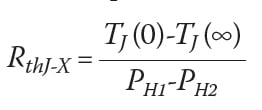
The thermal resistance is the steady-state value of the thermal impedance:
In practice, PH2 =~ 0,, therefore TJ(∞) = TX, thus classical definition of the thermal resistance provided by Equation (1) applies. Note, that with Equation (5) a new definition for the measurement of the thermal resistance is based on a differential approach. This approach has also been recommended by the JESD 51-14 standard for the transient method based RthJC measurements.
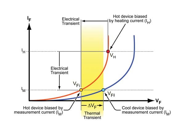
Figure 4 presents the transient processes shown in Figure 3 in the I-V characteristic. Switching the forward current suddenly from the IH heating current to the small IM measurement current the forward voltage would jump from the VH value to VFi – this later value will be the initial value of the forward voltage at the beginning of the cooling process. The change of the electrical operating point of the hot device from (VH, IH) to (VFi, IM) takes a finite period of time (determined by the electrical capacitances of the DUT & test equipment setup). During this tMD so called measurement delay time (indicated in Figure 3) there is a parasitic electrical transient, thus the data acquisition of the ΔVF(t) junction temperature transient induced forward voltage change at the constant IM measurement current has to be delayed. In practice the collected data points of the measured forward voltage transient corresponding to this parasitic electrical transient need to be discarded. The JEDEC JESD 51-14 standard [9] provides recommendations on how to separate the parasitic electrical transient from the real cooling transient and how to back extrapolate the missing part of the measured junction temperature transient to time t = 0. The implementation of the process is provided by a demo software tool forming an on-line Annex of the standard and is also available in professional, commercial implementations from thermal test equipment vendors.
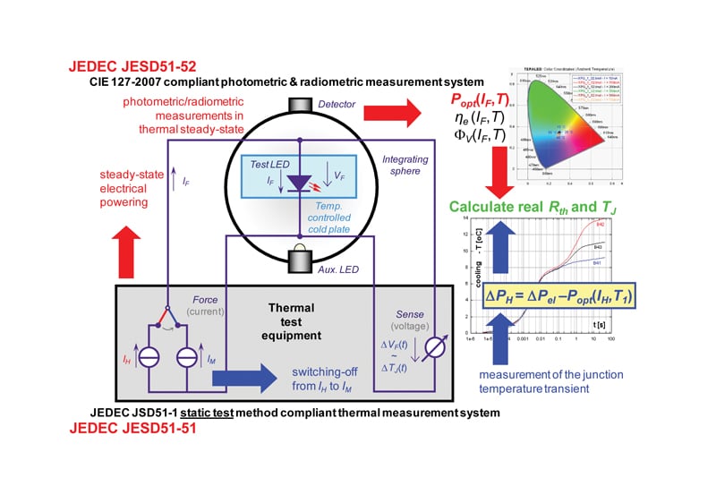
What is specific to LEDs in the measurement process is the period marked as ”stable” in Figure 3. This is an interval with a length appropriate for optical testing to measure the light output properties (including the radiant flux) of the test LED under steady state conditions as the LED light output measurement guidelines defined in the CIE 127-2007 standard [13] require. The summary of the complete measurement process required for the measurement of the real thermal resistance of power LEDs is provided in Figure 5.
THE NEW LED THERMAL TESTING STANDARDS
As discussed in the previous sections, measurement of the emitted optical power is vital when calculating the LEDs’ real thermal resistance (or thermal impedance if the dynamic thermal behavior is of interest). By neglecting the emitted optical power in this calculation the resulting thermal resistance / impedance value would be smaller – providing such (from marketing point of view more attractive) thermal metrics on LED data sheets can easily mislead customers and may result in improper design of the thermal management of the final LED application. This was the main motivation of the JEDEC JC15 committee when the work towards the definition of LED thermal testing standards commenced in 2008. Four standards have been worked out with the aim of fitting into the JESD 51-xx series of documents widely used in thermal characterization of packaged semiconductor devices. For LEDs the JESD 51-5x series of documents were published and April and May of 2012 and are summarized as follows:
- JESD 51-50: An overview document [4] that outlines the basic principles and possible future aspects of LED thermal characterization (including both testing and modeling). The document contains an overview chart which refers to the already published LED thermal characterization standards and includes foreseen topics of future standardization activities.
- JESD 51-51: This document [5] is the extension of the classical JESD51-1 standard [10] to the measurement of the real thermal resistance or real thermal impedance of power LEDs. When this standard is used in combination with the JESD 51-14 standard [9] (discussed in section 2.1), one can obtain the real junction-to-case thermal resistance of an LED package.
- JESD 51-52: This document [6] provides guidelines on how to apply the recommendations of the CIE 127-2007 standard regarding the measurement of the total flux of LEDs when such measurements are performed in combination with thermal testing of LEDs for the determination of the total radiant flux (emitted optical power). This JEDEC document also provides additional guidelines which were missing from the above CIE document.
- JESD 51-53: This document [7] is the glossary of terms and symbols used in the JESD 51-50 and 51-52 documents.
These new standards are essentially collections of definitions and additional recommendations / guidelines to prior standards such as JESD 51-1, JESD 51-14 and CIE 127-2007 which are needed for the correct thermal measurements of power LEDs. These additions are:
- It is recommended to use the RthJC junction-to-case thermal resistance measured in a JESD 51-14 compliant way to characterize power LED packages.
- In accordance with the JESD 51-14 standard it is recommended to measure power LED components attached to a cold plate.
- Since the energy conversion efficiency may strongly depend on temperature, it is recommended to use such a thermal testing procedure in which the measurement results are not significantly affected by this. Therefore the JESD 51-51 standard recommends measuring the cooling transient of the junction temperature (like it is also recommended in the JESD 51-14 standard). To assure reproducibility of the measurement results it is recommended to report the set temperature of the test environment (cold plate).
- In the heating power the measured Φe total radiant flux (also known as Popt emitted optical power) has to be considered – see Equation (2). This needs to be measured in a CIE 127-2007 compliant total flux measurement setup in such a way, that the test LED must be attached to the same temperature controlled cold plate as during the thermal test. It must be also assured that the “test LED – cold plate” remains intact between the thermal and optical measurements. In order to assure the consistency between the measured light output properties (total radiant flux, total luminous flux, color coordinates, etc) and the measured thermal metrics, it is recommended that during the total flux measurements the cold plate temperature is set to the same value as it was set for the thermal measurements.
- It is recommended to perform the thermal and radiometric/ photometric measurements in a single, combined setup (such as shown in Figure 5).
- When reporting the test results, besides the identified RthJA_real real junction-to-ambient (i.e. junction-to-cold plate) thermal resistance, the Tref reference temperature (cold plate temperature) and the TJjunction temperature calculated from these parameters with the following equation:(6) TJ = Tref + PH x RthJA_realThe reported test results should also include the measured emitted optical power and the energy conversion efficiency. It is also advised to report the (junction) temperature dependence of the measured light output properties, both by means of plots and numerical tables.
The scope of the JESD 51-51 and 51-52 standards is restricted to DC current-driven LEDs emitting light in the visible range. Measurement of the directly AC mains driven LEDs has specific issues. For an overview of these issues (which are being dealt with in the relevant technical committees such as JEDEC JC15, CIE TC 2-76) refer to e.g. section 4.7 of chapter 4 in [8].
CONCLUSIONS
In this paper, the concepts of the new JEDEC thermal testing standards relevant to LED thermal characterization have been introduced. These are the JESD 51-14 standard defining the so called transient dual interface method (TDIM) for the measurement of the junction-to-case thermal resistance of power semiconductor device packages with a single heat-flow path. This class of packages also includes most of the LED packages. The other set of standards is the JESD 51-5x series of standards, developed specifically for the correct thermal characterization of LEDs. The test setup suggested by these LED thermal testing standards is based on existing standards – the JESD 51-5x series of standards recommend to use a JESD 51-1 compliant thermal testing setup combined with a CIE 127-2007 compliant LED total flux measurement setup in order to account for the emitted optical power of LEDs during their thermal measurements. In such a setup the DC powering for both the thermal and optical test is provided by the thermal test equipment. The test LED should be attached to a temperature-controlled cold plate. This ensures reproducible thermal and light output measurements of LEDs.
The JEDEC LED thermal testing standards also include recommendations about data reporting. This is of key importance in order to assure that future LED product data sheets include information relevant for sufficient thermal design of the final LED application.
REFERENCES
[1] ANSI/IESNA IES Nomenclature Committee, IES RP-16-10, “Nomenclature and Definitions of for Illuminating Engineering”, ISBN 978-0-87995-208-2
[2] www.zhagastandard.org/
[3] C. J M Lasance, A. Poppe, “LED Thermal Standardization: A Hot Topic”, ELECTRONICS COOLING 15:(2) (2009), www.electronics-cooling. com/2009/05/led-thermal-standardization-a-hot-topic/
[4] JEDEC Standard JESD51-50, “Overview of Methodologies for the Thermal Measurement of Single- and Multi-Chip, Single- and Multi-PN Junction Light-Emitting Diodes (LEDs)”, www.jedec.org/sites/default/files/docs/jesd51-50.pdf (April 2012)
[5] JEDEC Standard JESD51-51, “Implementation of the Electrical Test Method for the Measurement of the Real Thermal Resistance and Impedance of Light-emitting Diodes with Exposed Cooling Surface”, www.jedec.org/sites/default/files/docs/JESD51-51.pdf (April 2012)
[6] JEDEC Standard JESD51-52, “Guidelines for Combining CIE 127-2007 Total Flux Measurements with Thermal Measurements of LEDs with Exposed Cooling Surface”, www.jedec.org/sites/default/files/docs/JESD51-52.pdf. (April 2012)
[7] JEDEC Standard JESD51-53 “Terms, Definitions and Units Glossary for LED Thermal Testing”, www.jedec.org/sites/default/files/docs/jesd51-53. pdf (May 2012)
[8] C. J. M. Lasance, A. Poppe (eds.) Thermal Management for LED Applications, New York Heidelberg Dordrecht London: Springer, (2013). (Solid State Lighting Technology and Application Series) ISBN: 978-1-4614-5090-0, DOI 10.1007/978-1-4614-5091-7
[9] JEDEC Standard JESD51-14 “Transient Dual Interface Test Method for the Measurement of the Thermal Resistance Junction-To-Case of Semiconductor Devices with Heat Flow Through a Single Path”, www.jedec.org/sites/default/files/docs/JESD51-14_1.pdf (November 2010)
[10] JEDEC Standard JESD51-1, “Integrated Circuits Thermal Measurement Method – Electrical Test Method (Single Semiconductor Device)”, www.jedec.org/sites/default/files/docs/jesd51-1.pdf (December 1995)
[11] D. Schweitzer, “Transient dual interface measurement of the Rth-JC of power semiconductor packages” ELECTRONICS COOLING 16:(9) (2010) www.electronics-cooling.com/2010/09/transient-dual-interface-measurement-of-the-rth-jc-of-power-semiconductor-packages/
[12] S. Müller, T. Zahner, F. Singer, G. Schrag, G. Wachutka, “Evaluation of Thermal Transient Characterization Methodologies for HighüPower LED Applications”, In: Proceedings of the 17th International Workshop on THERMal INvestigations of ICs and Systems (THERMINIC’11), 27-29 September 2011, Paris, France, pp. 104-109
[13] CIE 127-2007 Technical Report “Measurement of LEDs” (ISBN 978 3 901 906 58 9)
1 Zhaga call their distinct specification documents as books – this term is maintained in this article.
2Structure functions are the thermal capacitance – thermal resistance maps of the junction-to-ambient heat-flow path; the shape of the structure function depends on the thermal properties and the geometry of the subsequent sections of the heat-flow path. For details on structure functions see the original papers of V. Székely or consult Annex A of the JESD 51-14 standard [9] or see Sections 4.4.4 and 4.4.5 of chapter 4 in [8].
András Poppe was born in 1962 in Budapest, Hungary. He obtained his MSc degree in electrical engineering in 1986 from the Budapest University of Tecnology (BME), Faculty of Electrical Engineering. In 1996 he obtained his PhD from BME. In 1989-1990 he was a guest researcher at IMEC (Leuven, Belgium) where he was dealing with mobility modeling for the purpose of device simulation. Since 1990 he has been with the Budapest University of Tecnology, Department of Electron Devices. Since 1996 he has been working at BME as an associate professor. In 1997 he was one of the co-founders of MicReD (now Mentor Graphics Mechanical Analysis Division MicReD unit). His current responsibility at Mentor Graphics is product management of LED testing solutions.
Besides his academic and industrial activities he has been involved in various national and international research projects (e.g. EU FW7 Fast2Light, KÖZLED, EU FW7 NANOPACK and most recently the EU FW7 NANOTHERM). He is active in the international standardization work regarding LEDs: he is member of the JEDEC JC15, CIE TC2-63, TC2-64 and TC2-76 technical committees. His fields of interest include thermal transient testing of packaged power semiconductor devices, characterization of LEDs and OLEDs, electro-thermal simulation.

