Payam Bozorgi and George Fleischman
PiMEMS, Inc.
Introduction
As electronic system technology advances with continual increases in requirements leading to greater demand for higher power consumption, there have been growing challenges related to the design of thermal engineering and heat rejection technologies. The need for performance inevitably leads to operation of most electronic systems at the limits of the available thermal management technology. Today, one widely used method of thermal management in microprocessor and semiconductor chips is the heat pipe, due to its simplicity, reliability, practicality, and low-cost. However, conventional heat pipes have thermal transport and geometric limitations.
A thermal ground plane (TGP) is basically a flat heat pipe or vapor chamber type heat pipe. The TGP will expand upon the 2-phase cooling approach utilized in heat pipes and minimize issues relating to temperature gradients, increased weight, or added complexity. An important feature of the intended TGP technology is compatibility with existing chips and electronic devices without redesign of those systems; insertion of TGPs into these systems can provide new engineering margins yielding increased power use for the system, reduced operating temperatures, or reduced size of other components in the thermal management system.
Previous Approaches
Early attempts to use TGPs for cooling electronics can be traced back to the 1970s [1]. In retrospect, the path forward has indeed been elusive. At first, simple cylindrical heat pipes were embedded in copper or aluminum plates. The heat pipes were bonded into holes drilled into the plate material. These devices were on the order of 10 mm thick. They were heavy, and thermal conductance was poor (~0.1 W/cm2-°C) due to the bondline thermal resistance between the plate and the heat pipes. In an attempt to provide a thinner TGP, thin-wall cylindrical heat pipes were flattened, and bonded between two aluminum facesheets. Although these TGPs were thinner (~4 mm overall thickness), thermal conductance remained poor, because of the bondline between the heat pipes and facesheets. Moreover, these TGPs were not tolerant to internal temporal working fluid pressure variations caused by temperature. The thin-wall flattened heat pipes tended toward their naturally rounded configuration at high operating temperatures associated with qualification tests (>100°C) or high altitude aircraft and spacecraft applications (>80°C). This resulted in flexing the circuit boards and associated solder joints.
Subsequently, vapor chambers [2] were developed. The vapor chambers were basically flat heat pipes that eliminated the individually embedded heat pipes of the previous designs, thereby eliminating the bondline between these heat pipes and facesheets. Vapor chamber TGPs typically used fine mesh wire screens or sintered powdered wicks leading to high thermal resistance to conduct heat into the wick material, at high heat flux levels, and excessive blockage of vapor space. For manufacturing reasons these vapor chambers were constructed of copper. However, copper has relatively poor structural properties, and this approach resulted in thick (~5 mm), heavy units. Moreover, copper has a higher coefficient of linear thermal expansion (CTE) relative to silicon (namely, 16.7 ppm/°C versus 2.6 ppm/°C, respectively) resulting in delamination of components and cracking in solder joints.
The Titanium Based Approach
The titanium based thermal ground plane (Ti-TGP) [3] was developed in response to advanced portable semiconductor and aerospace applications that are searching for ultra-thin, flat, lightweight and reliable thermal solutions.
Titanium has superior mechanical and electrical properties compared to copper or other conventional materials that have been used in heat pipes, Table 1. Titanium has: i) higher strength to weight ratio, ii) CTE closer to silicon which provides an improved thermal match between silicon based chips and the thermal solution, iii) higher corrosion resistance and, iv) compatibility with water.
Although the thermal conductivity of titanium is relatively lower than copper, the vapor chamber facesheets can be made 3 to 4 times thinner than a copper TGP. Therefore, the temperature drop for conducting heat into or out of the panel is not significant. For example, for a given budget thickness of a 4 mm TGP, the facesheet of titanium can be as thin as 500 μm, while the copper facesheet is required to be 1.5 mm thick in order to withstand the vapor pressure. That provides a 3 mm vapor space for the titanium TGP, while a copper TGP can only have a 1 mm vapor space. The temperature drop across a titanium facesheet would be ~2.5°C for a heat flux of 10 W/cm2 compared with ~0.5°C for a copper TGP. This difference of ~2°C is a small penalty for the advantages of using titanium.

Generally, TGPs (flat vapor chambers) consist of two main structures; wick and back planes that are brought together, charged with working fluid, and sealed. The TGP cross-section and internal wick details are given in Figure 1. The overall thickness is calculated by adding the vapor space depth (VSDepth) to the thickness of the wick and the back planes (TWP and TBP) as shown in Figure 1a. For a given TGP thickness budget, the vapor space depth is determined based on the required thermal metrics regardless of the material used. However, the thickness of the wick plane (excluding wick depth) and back plane are dependent on the material. These are the only two parameters that can be used to reduce the overall thickness. The high fracture toughness and yield stress of titanium compared to copper or aluminum allows both TWP and TBP to be as thin as 150 μm without suffering mechanical failure, resulting in an ultra-thin TGP (600 to 900 μm) that can withstand the internal pressure of the working fluid.

The multi-scale fabrication capability of titanium is another attractive feature. It can be either macro-machined using traditional machining processes or, micro-fabricated using micro-patterned masks and wet or dry etching to fabricate features having dimensions of 5 to 100 μm, Figure 1(b). Titanium can also be coated with nanostructure on the micro-scale wicks to generate a super hydrophilic surface (~0° wetting angle). Wettability of the titanium-water interface is an important factor in wicking velocity, which drives heat flow rate. The wick surfaces are enhanced by a chemical process to generate a highly porous surface called Nano-Structured-Titania (NST) [6], with pore features on the order of 100nm, Figure 1(c). The Ti-TGP is then hermetically sealed by micro-laser welding. [3,5]
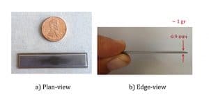
The Ti-TGP has been customized for heat load capacities from 1W up to 1KW [3] with thermal conductance of 45 W/°C and 27 W/°C, based on average evaporator and condenser temperatures, for thickness of 5 and 3 mm, respectively. Figure 2 shows an ultra-thin and portless Ti-TGP, weighing 1 gram with thickness of 900 μm and overall dimensions of 50 mm X 8 mm. Figure 2a is a photograph of the plan view, whereas Figure 2b shows the edge view of the actual TGP.

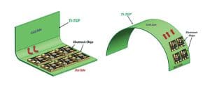
Another attractive feature of titanium is scalability and conformability that allows the Ti-TGP to be designed and fabricated into predefined 2D and 3D shapes (Figure 3).
Future Directions
A new generation of semiconductor and micro-electronics devices are operating at higher power densities and consequently generating higher heat flux (≥ 100 W/cm2) capability. These applications are beyond the heat load capacity of current passive flat thermal ground plane solutions.
The future of advanced thermal management is moving toward active solutions to push the heat flux limit beyond passive solutions. Adaptive ultra-thin titanium-based active piezoelectric driven solutions that are able to extend the heat flux limit up to 150 W/cm2 are currently being developed. Thermal solutions for SiC GaN MMIC are also currently being pursued with the aim of rejecting 1.2 kW/cm2 heat flux from the GaN MMIC.
In summary, a range of thermal solutions will be available to accommodate a wide range of power and heat flux requirements.
References:
1. A. Basiulis and T. A. Hummel, “The Application of Heat Pipe Techniques to Electronic Component Cooling,” ASME Winter Annual Meeting, New York, NY, Nov 1972, ASME Paper No. 72-WA/HT -42.
2. G. L. Fleischman, BD. Marcus, R. McIntosh, and S. Ollendorf, “Flat-Plate (Vapor Chamber) Heat Pipes,” AIAA 10th Thermophysics Conference, Denver, Co, May 1975, AIAA Paper No. 75-728.
3. M. Sigurdson, Y. W. Liu, P. Bozorgi, D. Bothman, and C. D. Meinhart, and NC. MacDonald, “A large Scale Titanium Thermal Ground Plane,” International Journal of Heat and Mass Transfer, 2013.
4. F. Aimi, M.P. Rao, N.C. MacDonald, A.S. Zuruzi, and D.P. Bothman, “High Aspect Ratio Bulk Micromachining of Titanium,” Nat. Mater. 3 (2004) 103–105.
5. P. Bozorgi, “Application of YAG Laser Micro-Welding in MEMS Packaging,” Nanotech 2010: Electronics, Devices, Fabrication, MEMS, Fluidics, and Computational, +, 2010, pp. 5-8.
6. Samah B. Butler, E. Parker, A. Ahmed, H. Evans, C. Safinya, N. MacDonald, “Integrating Biomaterials into Microsystems: Formation and Characterization of Nanostructured Titania,” Mat. Res. Soc. Symp., 2004.


