Introduction
While data enter energy consumption is already significant, the growth of a global cloud-based economy along with society’s need for constant social networking connectivity will cause this number to rise even further. The world’s Information-Communications-Technologies (ICT) infrastructure, a general representation of cloud-based computing, is estimated to consume 1,500 TWh of electricity, roughly 10% of global usage [1]. Datacenter power draws in the U.S. rose from 9,900 MW to 10,560 MW between 2012 and 2013, representing a 7% increase [2]. With the average American household consuming roughly 10,000 kWh of energy annually, the previously cited 2013 number represents nearly 3.8 million homes. Consumer demand for information, only part of why this number is increasing, shows no signs of slowing either. An interesting infographic published by Intel [3] shows how internet traffic is distributed in any given minute. Over 1,500 TB of data is distributed per minute globally with video streaming, primarily in the form of YouTube and Netflix, accounting for half of that traffic. All indications are that demand for social network connectivity and use of streaming video services will grow, resulting in even more requirements for data centers worldwide. The current study seeks to illustrate how data center power density, efficiency, and reliability can be increased through the integration of a two-phase liquid immersion cooling approach into a small form factor electronics enclosure meant to simulate a modular high-performance server assembly. The results, analyses, and conclusions of this work were presented at the 2014 SEMI-THERM conference in San Jose, CA [4]
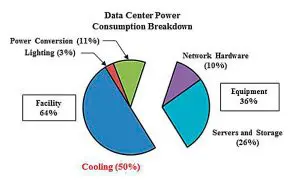
Figure 1 – Chart showing the significant resources a data center dedicates to the thermal management solution employed. [5]
As shown in Figure 1, half of the power consumed by a conventional air-cooled data center is dedicated to the thermal management solution utilized. Two-phase liquid immersion cooling techniques offer the opportunity to reduce cooling power consumption significantly through the use of the orders of magnitude increase in heat transfer coefficients (HTC’s) available with this solution [6]. Higher HTC’s result in lower thermal resistances, which can play a beneficial role in the overall system efficiency. Increasing the HTC also reduces the driving temperature difference from ambient necessary to remove the heat generated. Reducing this temperature promotes the reliability of the system as the failure rate of a processor is tied to the chip’s operating temperature. These significant increases in heat transfer coefficients are experimentally documented in practical applications with boiling from both bare silicon as well as from microscale surface enhancements attached to the wall of the heated element [7,8]. The translation of these performance parameters to power savings is also well documented. A data center in Hong Kong used dielectric fluids from the Novec family as part of a two-phase immersion solution based on an Open Bath Immersion (OBI) approach. This facility reported a cooling electricity savings of 95% and a Power Usage Effectiveness (PUE) of 1.02 [9]. Using a similar approach, a team of SGI and 3M have partnered to construct a facility to cool the former’s ICE X supercomputing hardware [10]. While these two-phase approaches are very much in the development stage, solutions where the immersion coolant is kept as a liquid are mature and commercially available. Companies such as Iceotope, LiquidCool Solutions, and Green Revolution Cooling all offer suitable single phase immersion-cooled solutions for current generation computing applications.
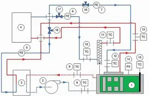
Figure 2 – Schematic illustrating the primary flow loops and components within the overall experimental setup. [4]
Experimental facility
Figure 2 is a schematic of the entire experimental facility used for the current work. The schematic also represents the framework of a liquid-cooled data center’s coolant delivery system. Many of the elements one would find in such an installation are represented here such as a chiller for system-level heat extraction, heat exchanger for immersion/external coolant interfacing as well as critical flow characteristic monitoring subsystems. All of these elements are identified within the schematic by the associated Find Numbers (FN’s) shown on the table within Figure 2. FN 1 represents the experimental cartridge assembly, the primary component within the facility as it houses the heated elements meant to simulate high-performance processing elements. These elements are sealed within an aluminum housing that has dimensions of 150 mm x 300 mm x 38 mm (H x L x W). Located at the top of the assembly is the chilled water header which is directly attached to a 4 x 21 array of fins that protrude down from the top inside face of the housing. The direct attachment is achieved through the machining of the aluminum housing out of a solid aluminum block, thus eliminating the need for a Thermal Interface Material (TIM) attaching the fins to the exterior header channels. This method of manufacture also reduces the number of potential leak points from which the dielectric fluid could dissipate as dielectric fluids have been known to escape from cracks as small as those made by welded joints. The internal fins capture the heat generated by the rising vapor from the boiling elements via condensation. The heat is then conducted into the walls of the chilled water header and subsequently convected away via the flow of an 80/20 by volume mixture of deionized water and Dowtherm SR-1 respectively being pumped through the channels. The chilled water header acts as the primary means by which is heat is removed from the cartridge under pool boiling conditions but can act as a supplement when subcooled dielectric fluid is pumped through the cartridge via the inlet and outlet ports shown to the left of FN 1 on Figure 2. Under this flow boiling scenario, the heat that is gained by the dielectric fluid flowing through the cartridge is extracted from the system by a liquid-liquid heat exchanger that interacts with a second branch of the previously mentioned coolant mixture. All of the facilities chilled water mixture is distributed and maintained to within a 0.1°C setpoint for all of the experiments conducted within this study by a primary chiller unit, shown as FN 4 on Figure 2. To maintain the intent of modularity in the design and the overall Line Replaceable Unit (LRU) approach, all connectors are of the quick disconnect style from the Colder Products LC Series. In order to maintain a good seal around the visualization windows of the enclosure, EPDM gaskets were used with great success over hundreds of hours of testing for both the Novec 649 and FC-72 fluids used. The fluid inventory sealed within the enclosure is minimal, slightly under 1L for pool boiling conditions. Attention must be paid as well to the sealing of the electrical I/O. Therefore, a Glenair hermetic connector from the 177-705H series was selected for this critical interface. This connector is located on the same plane as the dielectric fluid inlet and outlet ports. It is also important to ensure that the pressure within the electronics enclosure is monitored and maintained within an acceptable limit. Increasing the pressure within the assembly raises the saturation point, or boiling point, of the fluid which in turn increases the temperature necessary to initiate boiling. As mentioned previously, this increase in operating temperature will have a deleterious effect on the overall system reliability. The pressure for the current study is maintained at atmospheric conditions by a vented Graham condenser but, in an actual installation, could be done with a dedicated bellows as well.
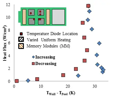
Figure 3- Plot showing the pool boiling results as heat flux is increased and decreased with FC-72 as the working fluid and 7 degrees Celsius as the facilities chilled water set point. The red squares on the image to the top left of the plot indicate where temperatures were measured for calculation of the average value presented. [4]
Pool boiling results
Figure 3 shows the variation of heat flux from the four primary bare silicon die with respect to the driving temperature difference, that between the average surface temperature of the heated elements and the pool temperature. Heat was applied to the elements and temperatures were measured using thermal test cells from the PST4 series by Kokomo Semiconductors. The maximum heat flux achieved is roughly 12 W/cm2. Remarkably, this number was achieved from a bare silicon surface facilitating the integration of any number of Commercial-Off-The-Shelf (COTS) available processing elements into the electronics enclosure. The hysteresis one would expect from a traditional pool boiling curve is evident in Figure 3 but with a slight variation. The double hitch is more than likely attributable to two factors. The first is the wide distribution of pore sizes one will find on a bare silicon surface and their consequent variation in activation in accordance with Hsu’s model. Secondly, the top die begin nucleation before the bottom die which would cause two distinct hysteretic phenomena as shown in Figure 3. A potentially more useful result was attained when pool testing was extended to four other facilities chilled water setpoints, namely 11°C, 15°C, 18°C and 22°C, with Novec 649 as the working fluid. Formulation of the data into power dissipated or heat transfer coefficient variation with respect to average surface temperature yielded no noteworthy differences. However, the data was compared to the well-known Rohsenow correlation using a Csf value of 0.0051 obtained from a more conventional pool boiling study [11]. Using this value, which is very close to the 0.0054 value found by Geisler [12] for bare silicon and FC-72, along with the properties shown in Table 1, the Rohsenow correlation predicted the heat fluxes yielded in the fully developed boiling regime from the current study for all of the chilled water set points to within ±40%, a generally accepted margin for two-phase correlations. It should be noted that the Rohsenow correlation is for a single heat source. The work of Kim et al. [13] was used to resolve the four die arrangement used in the current study into the single heat source geometry necessary for integration into the correlation.
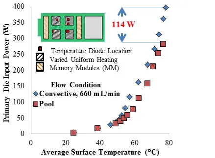
Figure 4- Plot showing the increase in maximum power dissipation available with the pumping of a slight amount of subcooled FC-27 fluid within the electronics enclosure. The red squares on the image to the top left of the plot indicate where temperatures were measured for calculation of the average value presented. [4]
Flow boiling enhancement
As shown in Figure 4, by introducing 660 mL/min of subcooled dielectric fluid flow, the maximum power dissipation achieved increases by over 100W, or approximately 40%, at the same chip operating temperature. For the results in Figure 4, the working dielectric fluid was subcooled by the facilities chilled water distributed by the chiller at a set point of 15°C. While adding pumping power increases the energy consumption of the overall thermal management solution, the increase in power density capabilities possible by adding this flow loop cannot be ignored.
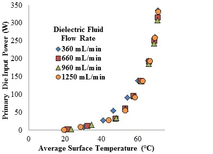
Figure 5- Plot showing the negligible effect of increasing the dielectric fluid flow rate on the average surface temperature of the primary die within the range of total power dissipations associated with the fully developed boiling regime. [4]
Increasing the dielectric fluid flow rate under the flow boiling scenario should have no effect on the fully developed boiling regime as the two-phase heat transfer occurring at the surface is dominant when compared to that attributable to forced convection. This concept is experimentally verified in the results of Figure 5 as the thermal performance curves merge for primary die power dissipations that are associated with fully developed boiling conditions across all of the dielectric fluid flow rates tested. While not experimentally illustrated as part of the current study, increasing the dielectric fluid flow rate in a flow boiling scenario does increase the maximum power dissipation that a heated surface can achieve before burnout. This has been shown in a recent work by the authors of the current study, and power dissipations in excess of 600W have been achieved from four similarly sized heated surfaces to the current study with the use of microporous surface enhancements [7].
CONCLUSIONS
The current study shows the practical application of liquid immersion cooling techniques to a high-performance server model with a limited footprint both in terms of the volume occupied and fluid reservoir required. Under pool boiling conditions a maximum power dissipation of slightly over 300W was achieved while over 100W more is available with the introduction of only a modest amount of subcooled dielectric fluid flow within the enclosure. The study has shown that power densities on the order of current generation processing elements and beyond can be easily handled at a significantly lower operating temperature than many of the more conventional air-cooled techniques can achieve. As consumer demand drives electronics into more compact form factors, the evolution of immersion-cooled studies will become increasingly important as resulting heat fluxes will necessitate matriculation to some form of two-phase liquid cooling.
References
[1] M.P. Mills. (2013, August). “The Cloud Begins with Coal August” [PDF]. Available: http://www.tech-pundit.com/wp-content/uploads/2013/07/Cloud_Begins_With_Coal.pdf
[2] DatacenterDynamics, (2014, January/February), “Is the Industry Getting Better at Using Power?,” Focus [Online]. Available: http://content.yudu.com/Library/A2nvau/FocusVolume3issue33/resources/index.htm?referrerUrl=
[3] Intel [Online]. Available: http://www.intel.com/content/www/us/en/communications/internet-minute-infographic.html
[4] J. Gess, S.H. Bhavnani, B. Ramakrishnan, R. W. Johnson, D. Harris, R. Knight, M. Hamilton and C. Ellis. (2014, March). “Investigation and Characterization of High Performance, Small Form Factor, Modular Liquid Immersion Cooled Server Model” Semiconductor Thermal Measurement and Management Symposium (SEMI-THERM), San Jose, CA.
[5] Info-tech Research Group [PPT]. Available: www.infotech.com/download/32455
[6] R.E. Simons. (1996, May 1). “Direct Liquid Immersion Cooling for High Power Density Microelectronics” Electronics Cooling [Online]. Available: https://electronics-cooling.com/1996/05/direct-liquid-immersion-cooling-for-high-power-density-microelectronics/
[7] J. Gess, S. Bhavnani, B. Ramakrishnan, R.W. Johnson, D. Harris, R.W. Knight, M. Hamilton and C. Ellis. (2014, May). “Impact of Surface Enhancements Upon Boiling Heat Transfer in a Liquid Immersion Cooled High Performance Small Form Factor Server Model” in Proc. of the 14th intersociety on thermal and thermomechanical phenomena (ITHERM), Orlando, FL.
[8] P. Tuma. (2006, Feb 1). “Indirect Thermosyphon for Cooling Electronic Devices” Electronics Cooling [Online]. Available: http://www.electronics cooling.com/2006/02/indirect thermosyphons for cooling electronic-devices/
[9] A. Becker. (2013, Dec 5). “Bitcoin Mining Boosts Interest in Liquid Cooling” Electronics Cooling [Online]. Available: https://electronics-cooling.com/2013/12/bitcoin-mining-boosts-interest-liquid-cooling/
[10] R. Miller, (2014, April 9). “New from 3M: Boiling Liquid to Cool Your Servers” Data Center Knowledge [Online]. Available: http://www.datacenterknowledge.com/archives/2014/04/09/new-3m-boiling-liquid-cool-servers/
[11] B. Ramakrishnan, S. Bhavnani, J. Gess, D. Harris, R. Knight and R.W. Johnson. (2014, March). “Effect of System and Operational Parameters on the Performance of an Immersion-Cooled Multichip Module for High Performance Computing” Semiconductor Thermal Measurement and Management Symposium, 2014, San Jose, CA.
[12] K.J.L. Geisler. (2007). “Buoyancy-Driven Two Phase Flow and Heat Transfer in Narrow Vertical Channels” (Doctoral Dissertation).
[13] Y.H. Kim, S.Y. Kim and G.H. Rhee. (2006, May-June) “Evaluation of Spreading Thermal Resistance for Heat Generating Multi-Electronic Components,” Thermal and Thermomechanical Phenomena in Electronics Systems, 2006. ITHERM ’06. The Tenth Intersociety Conference, San Diego, CA.

