
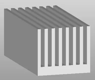
 This is what a typical extruded fin heatsink looks like. It’s made of metal and sits on top of IC packages that themselves are soldered to a PCB. It cools those packages by providing an increased air apparent surface area with which to pass on the heat that has been conducted up through it. Its shape (topology) is in most ways set by the manufacturing process used to create it. In this case, squeezing molten aluminum through a die with that shape as the profile. Similar constraints exist for other manufacturing processes, be it milling, casting, brazing, etc. 3D printing removes many of these constraints and, as the technology matures, I believe all of them will be addressed. So, with a process that can print any 3D shape, how should design tools adapt to such an opportunity?
More specifically, how could you use simulation to identify an arbitrary heatsink topology that is thermally efficient?
The/an answer turned out to be very simple:
- Start with a minimal section of heatsink base, a thin sliver.
- Simulate to see how hot it gets
- Where its surface is hottest ‘grow’ the geometry there by a very small amount
- GoTo 2
- Repeat until a design space has been filled
We applied this novel process to a forced convection cooled environment and chose a full length ‘rod’ shape as the ‘very small amount of geometry’ with which to grow the heatsink. Here are the first 5 steps of the additive design method (simulated with FloTHERM of course!):
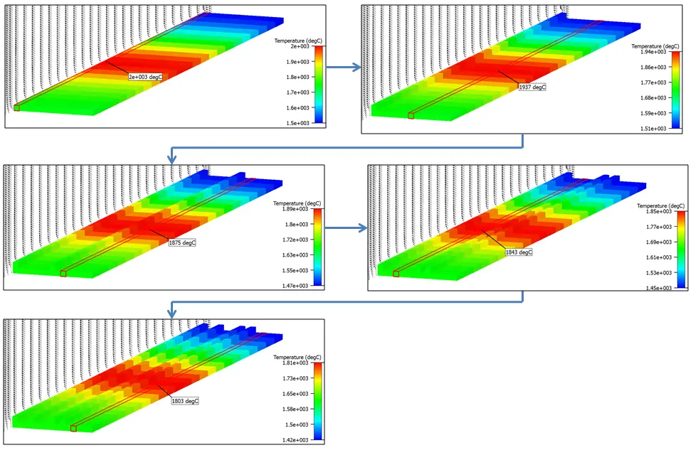
Each time the heatsink geometry ‘grows’, its thermal efficiency improves, the temperatures drop. That’s the intention of increasing the surface area at the hottest point, the point at which heat is bursting to get out. By growing the geometry at that point the thermal bottleneck is relieved, bit by bit.
To visualize the rest of the growth we change to a 2D front view and animate the sequential additions. A graph also shows the gradual improvement in thermal performance, a decrease in the heatsink thermal resistance, calculated as ((Base center temperature – ambient temperature) / Power):
We’ve already introduced organic words such as ‘growth’ and it’s evident that the heatsink bears more than a passing resemblance to a type of tree. Shoots are going up, they branch so as to enter more of the design space volume. If this first year of growth sees the heatsink establishing its main canopy, then subsequent years will see the formation of a trunk and thickened branches. 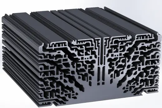 Over the next few blogs in this series, I’ll show how we go from this initial shape right up to a final automatically identified topology. I’ll also touch on Bejan’s Constructal Law, fractal geometry, methods of 3D printing metal alloys and how this additive design methodology might be refined and applied to a wider range of design challenges.
If you can’t wait then check out the recently published Semitherm 31 paper “An Additive Design Heatsink Geometry Topology Identification and Optimisation Algorithm. Robin Bornoff, John Parry, Mentor Graphics, UK” which should be on IEEE Xplore in the near future. It also won 3rd best paper at Semitherm! Yay
Manufacturing is changing, so must design.
24th March 2015, Ross-on-Wye

