 Cooling and thermal management are critical to data center reliability. Many organizations see cooling as a differentiating factor in the lifecycle cost of their data center. Recent industry guidelines [1] for data center cooling have suggested energy savings in air-cooled data centers by increasing the temperature of the cooling air. This increase enables two trends: reduced refrigeration power at higher refrigeration system evaporator temperatures and an increased number of hours available for using free-cooling. Free-cooling uses ambient air to provide cooling to the data center and reduce or eliminate the need for mechanical refrigeration. However, often overlooked is the significant power used in data centers for moving the cooling air. This article will use a simple thermodynamic and heat transfer analysis to highlight how trade-offs in Information Technology (IT) system power, computer room air conditioner (CRAC) fan power, and refrigeration power must be balanced to optimally operate the data center. Prior studies [2, 3, 4] have illustrated how simple models can be very effective at elucidating meaningful results.
ESTIMATING THE AIR FLOW IN A DATA CENTER
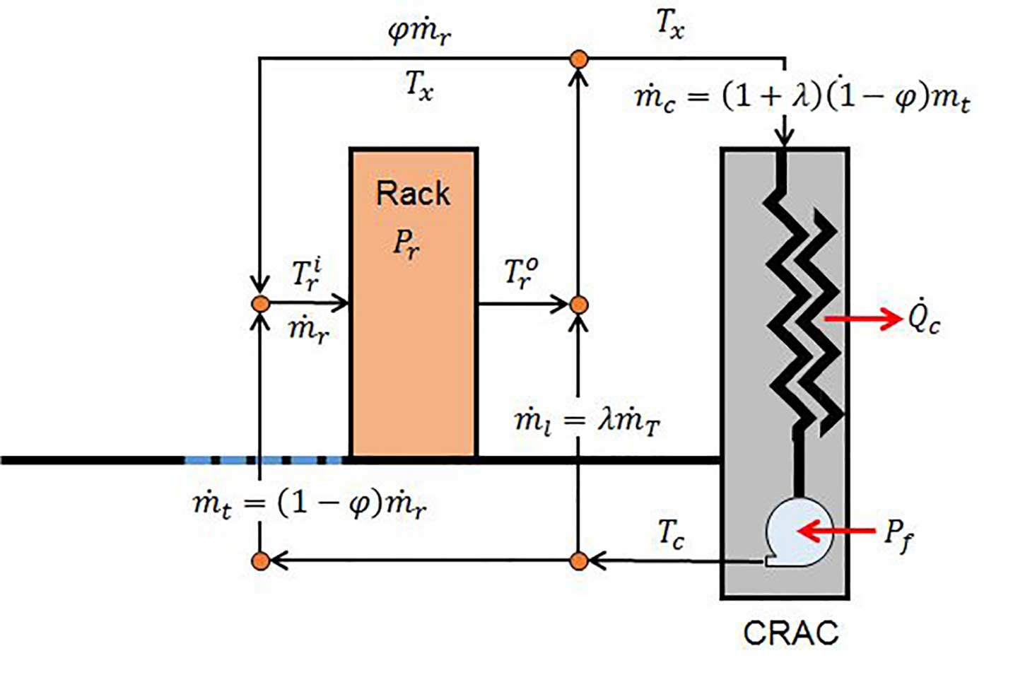
Referring to Figure 1, which shows a diagram of a simple model of an air-cooled data center, the cold air emanating from the CRAC (at temperature TC ) is divided into an active cooling portion mt and a leakage component λmt, which bypasses the cold aisle and blends with the IT rack’s exhaust air. The leakage could represent air that escapes through cable cutouts or through gaps in the raised-floor. The IT rack consumes a given power Pr , which is a combination of the power required by the electronics and the power of the IT system’s cooling fans. The cooling air that enters the IT rack is a combination of air supplied by the CRAC to the cold-aisle and a fraction, φ, of hot exhaust air that is recirculated back to the front on the IT equipment at the temperature of the CRAC return air, Tx.
Figure 1 – Schematic of a Simple Model of an Air-Cooled Data Cente
A mass and energy balance at the inlet of the IT rack shows that the rack inlet temperature must satisfy,
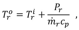
The inlet air, after being heated by the electronics, exits the rack at a temperature,
where cp is the specific heat of the air. The rack’s exhaust air mixes with the leakage air to form the data center exhaust air. The data center exhaust temperature, which is both the recirculated air and the CRAC inlet air temperature, is given by an energy balance on the exhaust node as,
Equation 1 can be combined with Equation 3 to show that the data center’s exhaust temperature must also satisfy,
Lastly, an energy balance of the CRAC shows that the CRAC supply temperature must satisfy,
DATA CENTER COOLING POWER CONSUMPTION
The data center CRAC cooling power, Pc , is comprised of two components: a refrigeration component that is expected to be higher with a lower CRAC supply temperature and an air moving component that is expected to vary with the air flow rate as,
where, Nc is the number of identical CRAC units in the data center, Kc is the CRAC pressure coefficient, ηf is the overall fan efficiency, assumed to be driven by variable speed motors, and Vc is the total CRAC volume flow rate. The refrigeration power consumption can be computed from,
where, Qc is the CRAC’s cooling requirement and COP is the refrigeration system’s Coefficient of Performance. It can be obtained from an energy balance of the data center. Therefore, the total cooling can be computed as, Pc=Pref+Pf .
OPTIMIZED COOLING FOR AN ENCLOSEDAISLE DATA CENTER
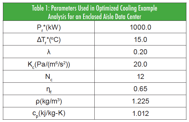
As an example, let’s assume that the data center has implemented cold-aisle containment [2, 5]. Theoretically, in an enclosed aisle data center, the air provided through the perforated tiles must equal the air required by the racks (i.e., φ = 0.0). The above set of equations can be used to parametrically study the optimal operating condition, given values of λ, Kc, ηf ,the variations of rack power and rack flow rate, and the variation in the CRAC COP. Table 1 provides the parameters used in the analysis.
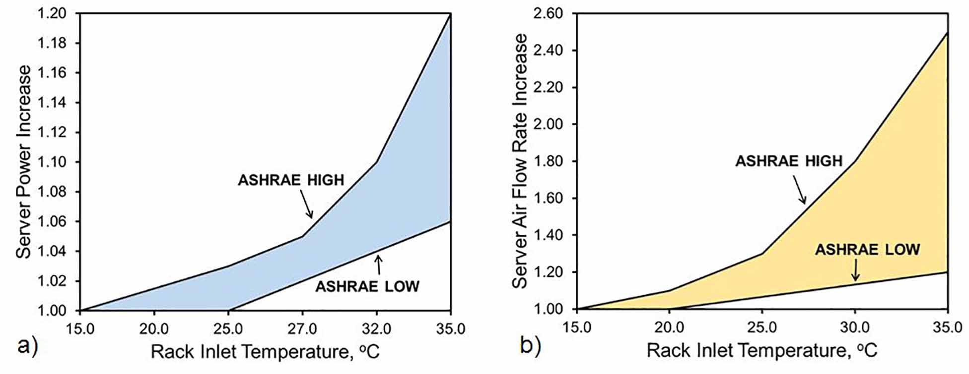
The variation in rack flow rate and power is not straightforward and the design varies from manufacturer to manufacturer. This example uses the relationships provided by ASHRAE [1], which have been reproduced in Figure 2, which shows that, as a function of inlet temperature, the required power and air flow rate can increase by 20% and 250%, respectively, as the inlet temperature is increased from 15 to 35oC. The figures also highlight the variation in IT equipment design by expressing the relationships as a band, with high performance and highly utilized servers as the upper limit (ASHRAE HIGH) and lower-utilized, lightly-configured servers as the lower limit (ASHRAE LOW). To use these figures, we will prescribe the rack power, Pr* , at 15oC and the server’s temperature rise ΔTr* at 15oC. The required rack flow rate at 15oC can then be computed from Equation 2. With the IT equipment characteristics defined at 15oC, the trends in Figure 2 can be used to find the power and flow requirements at higher inlet temperatures. For the CRAC performance, we will use the simple relationship described in [6], which expresses the CRAC COP as a monotonically increasing function of the CRAC supply temperature.
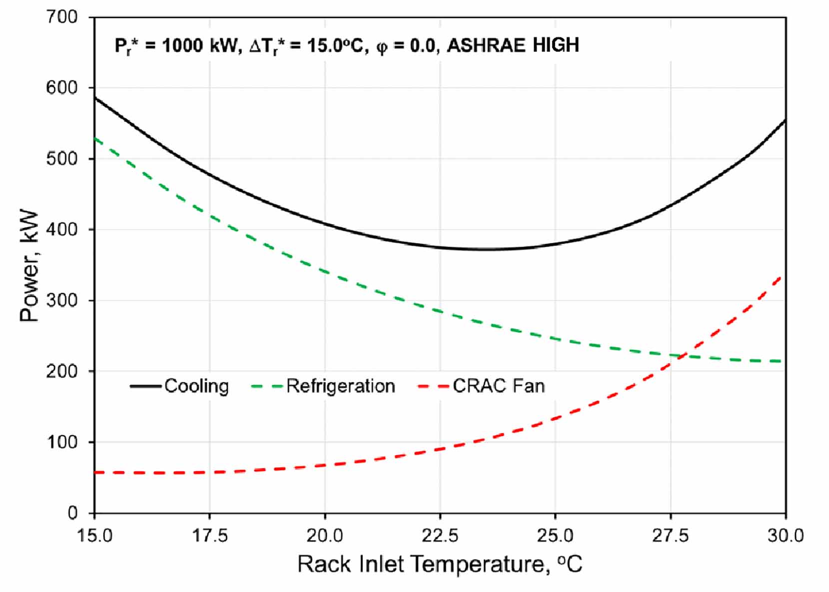
Using Equations 1 – 7, the relationships in Figure 2, and the parameters defined in Table 1, the data center’s cooling power requirement can be computed as a function of rack inlet temperature. Figure 3 shows the cooling power as the rack inlet temperature is varied from 15 to 30oC. It shows that the optimum operating point (i.e., the point with lowest cooling power consumption) occurs around 23oC. The figure shows the trade-off that data center operators should consider. Increasing the inlet temperature increases the amount of power and airflow required by the IT equipment and thus the amount of air that must be delivered by the CRACs. Even though the increased temperature enables a reduction in refrigeration power, this reduction is not sufficient to overcome the increased power requirement of the CRAC fans. Exclusive focus on reducing refrigeration power consumption without regard to the power consumed in moving the cooling air would lead to suboptimum and possibly misleading results.
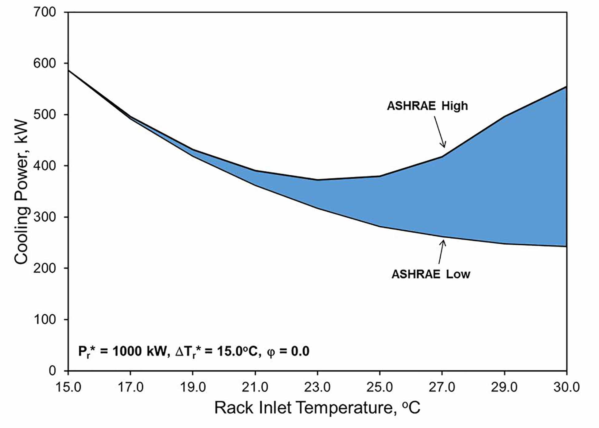
Figure 3 highlights the trend in cooling power for ASHRAE high-power and highly-utilized IT equipment. Using the trends from ASHRAE in Figure 2, Figure 4 shows how the design of the server’s cooling algorithm, utilization, and power consumption can impact the data center cooling optimization. High-performance and/or highly-utilized servers exhibit a clear data center minimum power consumption point; whereas, lower-utilized and/or lightly-configured servers, which have lower air flow requirements, exhibit their minimum data center power consumption point at higher inlet temperatures. Interestingly, for this class of servers, the reduction in power consumption beyond 24oC is relatively small, compared to the savings going from 15oC to 24oC. Since uptime and reliability are paramount to data center design, a designer may consider operating at a lower temperature and sacrifice small energy savings, to provide more resiliency in the event of a cooling failure.
This article shows how a simple thermodynamic and heat transfer model can be useful in determining the most efficient manner for cooling IT servers in a data center. It highlights the trade-off between refrigeration power and air moving device power, that data center operators need to consider in order to optimize their data center’s cooling system. Hopefully, this article offers the reader a methodology that can be considered at the early design stage of any thermal-fluid system in order to fully understand the problem at hand, before considering more detailed and time-consuming techniques.
REFERENCES
[1] ASHRAE, 2012, Thermal Guidelines for Data Processing Environments, 3rd Edition, Atlanta.
[2] Demetriou, D.W., Khalifa, H.E., 2012, “Optimization of Enclosed Aisle Data Centers Using Bypass Recirculation,” Journal of Electronics Packaging, Vol. 134, 020904.
[3] Khalifa, H.E., Demetriou, D.W., 2010, “Energy Optimization of Air-Cooled Data Centers,” Journal of Thermal Sciences and Engineering Applications, Vol. 2, pp, 041005-1:13.
[4] Simons, R.E, 2007, “Using a Simple Air Recirculation Model to Explore Computer Rack Cooling,” Electronics Cooling. https://electronics-cooling.com/2007/02/using-a-simple-air-recirculation-model-to-explore-computer-rack-cooling/, last accessed April 25, 2015.
[5] Muralidharan, B., Shrivastava, S. Ibrahim, M., Alkharabsheh, S., Sammakia, B., 2013, “Impact of Cold Aisle Containment on Thermal Performance of Data Center,” Proceedings ASME InterPACK, Vol. 2, Burlingame, CA, July 16 – 18.
[6] Moore, J., Chase, J., Ranganathan, P., Sharma, R., 2005, “Making Scheduling “cool”: Temperature-aware Resource Assignment in Data Centers,” in 2005
