By: Chandan K. Roy1, Sushil Bhavnani1, Michael C. Hamilton2, R. Wayne Johnson3,
Roy W. Knight1, & Daniel K. Harris1
1 Department of Mechanical Engineering, Auburn University, Auburn, AL
2 Department of Electrical and Computer Engineering, Auburn University, Auburn, AL
3Department of Electrical and Computer Engineering, Tennessee Tech University, Cookeville, TN
Introduction
As the power density of microelectronics steadily increases, thermal management continues to play a key role in the continuous march towards miniaturization, performance improvements, and higher reliability demands [1]. One crucial thermal management consideration in electronics packaging involves reducing the thermal interfacial resistance between devices and their adjoining heat sink or substrate through improvements in thermal interface materials (TIMs). In a high power package, the thermal resistance of the TIM can account for as much as 50% of the overall thermal resistance [2]. Any desirable TIM candidate material would need to have a high thermal conductivity, low thermal resistance at a thin bond line thickness (BLT), excellent wetting properties, and all at a low cost while also being environmental and health friendly [3]. In addition to thermal considerations, mechanical considerations of TIMs are equally important to the performance and health of high power electronics. TIMs can be either compliant (e.g. greases and gels) or non-compliant (e.g. solders and adhesives), where the former bears no interstitial mechanical stress due to thermally induced strains. Non-compliant TIMS must be able to withstand the mechanical stresses from coefficient of thermal expansion (CTE) mismatches between the adjoining materials (e.g. silicon – copper). If the CTE strain overwhelms the mechanical properties of the TIM, the joint will ultimately fail. Therefore, high performing compliant TIMS are a desirable design option for better thermal performance and improved reliability.
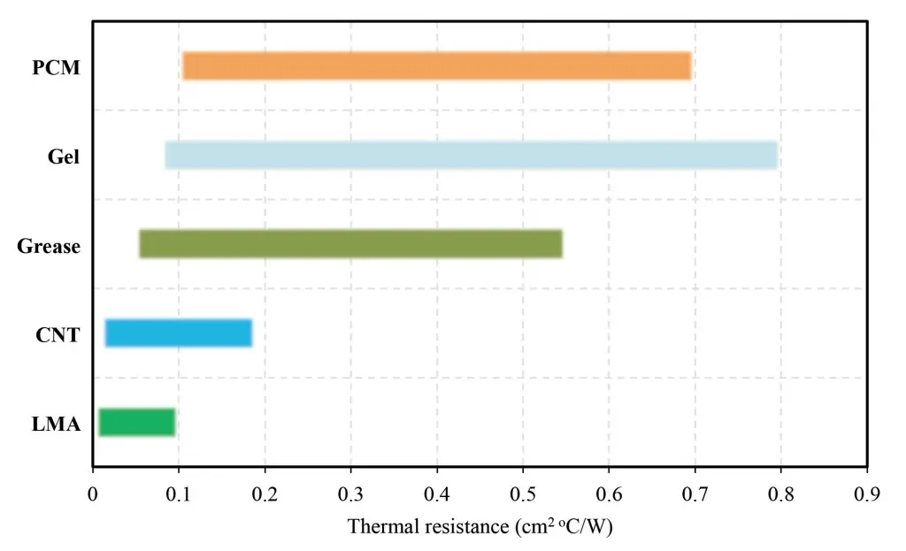
Commonly used commercially available TIMs include greases, phase change materials (PCM), gels, and pads, which are polymer based materials loaded with conductive particles (metal or ceramic) to enhance the thermal conductivity. Greases are the most widely used TIMs. However, greases are known to be messy, difficult to apply and remove due to their high viscosity, and have reliability issues such as pump out, phase separations, and dryout, which can limit the use of greases as a reliable TIM [3-4]. Carbon-based materials such as carbon nanotubes [5] and graphene [6] have been investigated by many researchers for use in TIMs. The thermal performance of different commercial and emerging TIMs based on previous research works is presented in Figure 1.
Figure 1 – Thermal performance comparison of variety of commercial TIMs with emerging TIMs such as CNTs and LMAs [4,5,7,10,12,13].
Recently, several researchers [7-9] have encouraged using liquid metal alloys (LMAs) as compliant, high performing TIMs. LMAs possess the requisite high thermal conductivity (an order of magnitude higher compared to the traditional TIMs) while also offering adequately low (<0.1 cm2oC/W, Figure 1) thermal resistances at small contact pressures. LMAs can be used either as a thin foil or in combination with a substrate [8-10] or as a filler material in composites [11]. Alloys of indium, bismuth, gallium, and tin are preferable to use as TIMs [8-10]. Mercury, lead and cadmium based alloys are usually avoided due to their toxicity and environmental issues. Hamdan et al. [7] reported the thermal resistance of liquid mercury microdroplets as low as 0.0025 cm2°C/W. However, mercury should be avoided due to its toxicity. Webb and Gwinn [8] observed that cycling 20oC above the melting point of the alloy (51In/32.5Bi/16.5Sn) resulted in a significant increase in the thermal resistance. However, Hill and Strader [9] did not find any notable performance degradation after cycling 90oC above the melting point of the same alloy (51In/32.5Bi/16.5Sn). Thus, a good understanding of the reliability of LMAs as TIMs is needed for today’s designers considering their use.
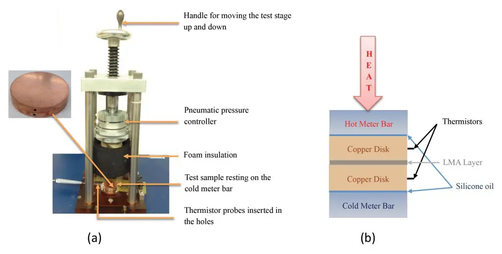
Figure 2 – (a) Testing of LMA TIM using modified test rig; the copper disks assembly with the TIM at the interface was placed between the TIM tester surfaces (b) Schematic diagram of the testing methodology.
Although LMAs offer a low thermal resistance, there are several concerns such as oxidation/corrosion, intermetallic growth, dewetting and migration. Several investigators have offered different approaches to mitigating these concerns [8-10]. In this work, three alloys were chosen to test their performance as TIMs. The properties of these alloys are presented in Table 1. These alloys were selected for study because they have a wide range of MPs (from 16oC to 60oC) spanning the range of interests for most application in today’s markets.
Experimental
Description of the apparatus
The thermal performances of the LMAs reported here were generated using an ASTM D5470 standard TIM tester. The detailed specifications of the apparatus used can be found in reference [14]. To avoid any contamination of the TIM tester surfaces and to improve the accuracy of the test results, the LMAs were tested by placing them between copper disks (alloy 110) of thickness 3.2 mm and 33 mm in diameter. The disks are both sides polished with a surface flatness within 7-8 microns. This high level of surface finish was needed for accurate thermal performance measurement but it is not required in actual application. However, it should be noted that the quality of the mating surfaces directly affects interfacial thermal performance. The resulting disk assembly with the alloy at the interface was then placed under the tester, Figure 2. Silicone oil (Xiameter PMX-200, viscosity: 1000CS) was applied on the top and bottom surfaces of the adjoining copper disks to ensure reproducible contact between the test surfaces of the TIM tester and the copper disks. The temperature differential (ΔT) across the LMA bond line was measured using two high precision thermistor probes (1 mm dia., accuracy 0.05oC) inserted in the middle of each copper disk. The hole was filled with thermal grease (laird tech. Tgrease 880) to ensure reproducibility of the measurements.
Sample preparation and diffusion barriers
The oxide layers on the copper disk surfaces were first chemically removed using methanol, acetone, and a 5% hydrochloric acid solution prior to application of the LMAs. This method of surface preparation was sufficient for testing purpose, but not necessary for normal applications. To enhance the wetting, the disk surfaces were mechanically scrubbed with the alloy using cotton swabs. In the case of Ga and In-Bi-Sn alloy, both the alloy and the disk were heated above the melting point of the alloy after which the molten metal was applied onto the heated disk’s surface using a brisk mechanical rubbing application technique.
Since LMAs are known to react with and form intermetallics with Cu [8-10], surface treatments were used in order to retard the diffusion of the alloy components into the disks. Hence, a thin metallic barrier layer was applied on the copper disk surfaces by sputtering. As tungsten (W) provides superior protection against gallium (Ga) and Ga-based alloys, the copper disks were coated with 2 mm W. For better adhesion of the W, a 50 nm layer of titanium (Ti) was first applied.
RESULTS
In-Situ Thermal resistance
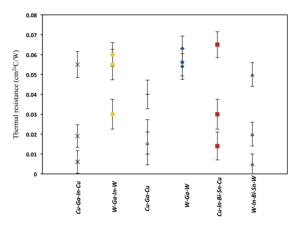
The thermal resistances of six different substrate-alloy combinations is presented in Figure 3.
Figure 3 – In-situ thermal resistances of three alloys between Cu and W surfaces at 138 kPa.
Three samples of each combination were tested at 138 kPa. The calculated experimental uncertainties [15] are represented by the error bars. Each resistance value presented here is the average of three repeated measurements. The measured lowest resistance was as low as 0.005 cm2°C/W with W/In-Bi-Sn/W (In-Bi-Sn alloy between W coated surfaces) and as high as 0.065 cm2°C/W with Cu/In-Bi-Sn/Cu (alloy 3 between bare Cu surfaces). The variation in thermal resistance for the similar substrate-alloy combination results from the unique nature of each sample. Since LMAs are highly conductive and the joints are relatively thin (SEM cross-sectional analysis reveals that the BLT of Cu/Ga-In/Cu joint is about 37 µm), the contact resistances (mostly due to surface irregularities such as surface roughness and flatness) dominate the interfacial resistance. Even a small change in surface properties would result in observable changes in the overall thermal resistance. It was assumed that all the disks had the same degree of surface roughness and flatness, but this is not valid in reality. It should be noted that it was not possible to maintain the exact amount of LMAs at the interface for each pair of disks during testing. Another source of variation might appear from the mechanical rubbing (wetting) of LMAs onto the disk surfaces. During the wetting process, it was found that some samples were more easily wetted while others required hard scrubbing to induce wetting. If the LMAs do not wet the mating surfaces properly, small air pockets might be present at the interface, which in turn increases the thermal resistance. Other properties of the alloys such as viscosity, surface tension, and oxidation state during application may have caused some variation in the thermal resistance measurements. Considering all these factors, each disks pair is different and it is a challenge to reproduce the result even with similar substrate-alloy combination.
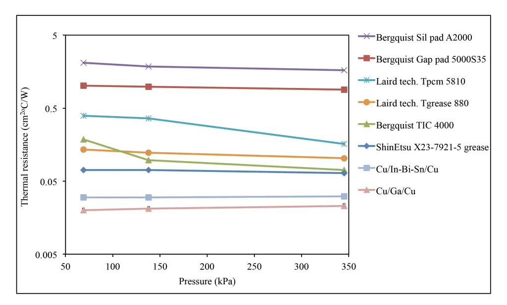
Figure 4 – Thermal resistances of variety of commercial TIMs and LMAs as a function of applied pressure.
The thermal performance of LMAs and some commonly used commercial TIMs are tested at different pressures using the same apparatus and similar methodology and measurements are compared (Figure 4). The results indicate that the thermal resistances of LMAs are independent of applied pressures in the range 69-345 kPa. This study concludes that LMAs offer excellent thermal bond even at a small pressure. None of the commercial TIMs were found to have a thermal joint resistance as low as the resistances of LMAs. Current high conductivity greases can offer resistances at the high end of what LMAs offer. The thermal resistances of the commercial TIMs tested were found to be as low as 0.065 cm2oC/W and as high as 2 cm2oC/W depending on the type of material being tested.
Isothermal aging
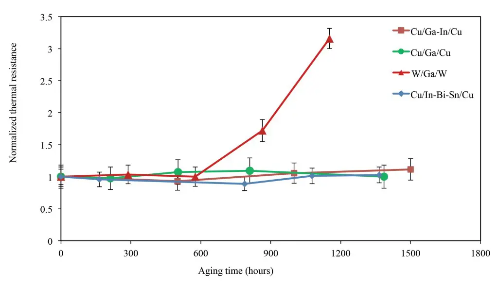
Accelerated aging was carried out by exposing the samples at an elevated temperature of 130oC (followed DARPA’s Thermal Management Technologies (TMT) program’s reliability profile [16]) in an atmospheric furnace for extended periods of time with no additional pressure and/or constrain during aging. The thermal aging test results of Ga between different substrate surfaces (Cu and W) and Ga-In and In-Bi-Sn alloys between Cu surfaces are presented in Figure 5.
Figure 5 – Isothermal aging (at 130°C) of three alloys as a function of aging time.
The thermal resistances are normalized by the initial resistance values. It was found that the thermal resistance of all three alloys between bare Cu remained unchanged after long periods of exposure (1500 hours for Ga-In alloy), which indicated a stable thermal joint. Ga between W surfaces also showed a negligible change in thermal resistance up to 576 hours of aging. However, the resistance started to increase rapidly thereafter. The thermal resistance increased by about 220% after 1152 hours of aging. The superior aging performance of all three alloys between bare Cu surfaces is believed to be due to the enhanced wetting of the alloys with Cu and the diffusion of the alloy into the Cu substrate. Since the alloys contain Ga and In, they will most likely diffuse into Cu and form intermetallics [9,10]. Our results suggested that any diffusion and formation of these intermetallics that may have occurred did not negatively impact the thermal performance over time. Since the thin layer of W acted as a diffusion barrier, the alloy could not interact with the underlying Cu substrate, thereby, causing the thermal resistance to increase significantly upon aging.
Thermal cycling
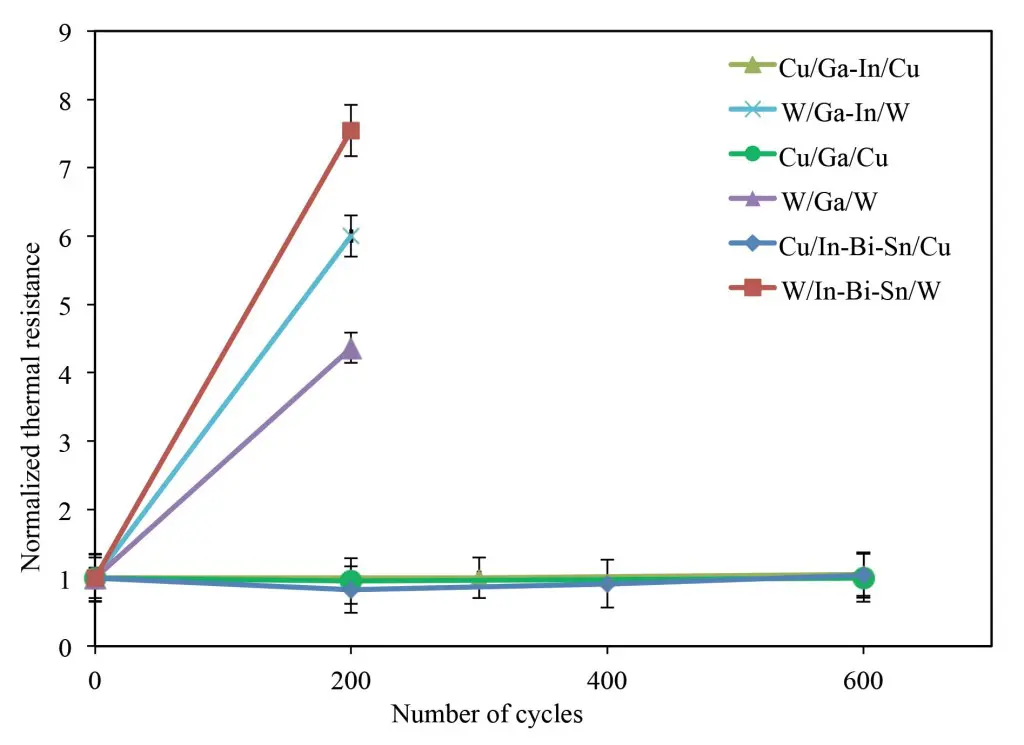
The purpose of these tests is to cycle each sample above and below the melting point of the interfacial alloy. The Cu disk assembly with alloys at the interface was placed in a thermal cycling chamber to cycle from -40oC to 80oC [16] with no additional pressure and/or constrain. The heating and cooling ramp rates were 3oC per minute. The samples were soaked for 20 minutes at the two extreme temperature plateaus, ensuring that the interface reached the chamber temperature. The time needed to complete a thermal cycle was two hours. Figure 6 shows the thermal cycling results of all three alloys between bare Cu and W surfaces. The results showed that the thermal resistance of all three alloys between bare Cu did not change significantly even after 600 cycles. However, alloys placed between W coated surfaces, the resistance increased significantly just after 200 cycles. It can be noticed from the aging studies (Figure 5) that the thermal resistance of Ga between W surfaces started to increase after 576 hours. However, the resistance increased significantly just after 200 cycles (400 hours). This is because, during aging tests, the samples were always kept at a constant temperature, whereas during cycling, the samples experienced thermal expansion/contraction resulting from the heating and cooling of the joint. All these results suggest that the bare Cu-alloy surface combination makes a more reliable LMA thermal joint.
SUMMARY AND CONCLUSIONS
The application of LMAs as efficient TIMs has been investigated herein. Three alloys (Ga-In, Ga, In-Bi-Sn) with different melting points and various compositions were chosen to test the thermal performance. The thermal resistances of the alloys were tested by placing them between bare Cu and W coated Cu substrates using the ASTM D5470 standard methodology. The in-situ thermal performance shows that LMAs can offer extremely lower thermal resistances at small contact pressures compared to many commercial TIMs. Accelerated tests include isothermal aging at 130oC and thermal cycling from -40oC to 80oC. It was observed that all the alloys between bare Cu surfaces survived both isothermal aging and thermal cycling. However, alloys applied between W coated surfaces failed to withstand both aging as well as cycling. The results indicate that any Cu-alloy interactions (which is primarily the diffusion and interfacial reaction) produce a more reliable thermal joint.
Figure 6 – Thermal cycling (-40°C to 80°C, 3°C/min, dwell: 20 minutes, 2 hours/cycle) of three alloys between Cu and W surfaces.
In actual processor-heat sink application, the LMAs are placed between two dissimilar materials, typically silicon (die) and copper (heat sink). In this work, LMAs are found to be effective when applied between bare Cu substrates. LMAs are thin liquids in molten form and they can accommodate any thermomechanical stress that results from the CTE mismatch of different materials. Therefore, it is presumed that they will continue to perform reliably between dissimilar material joints. LMAs are environmental and health friendly unless they contain any mercury, lead or cadmium compounds. They are easy to apply and commercially available, thus manufacturing at high volume would not be a concern. Many widely used commercial TIMs are greases or highly solid-loaded pastes that have a high viscosity and in some cases shear harden which makes these types of TIMs more difficult to apply and rework. LMAs are not only more compliant and less viscous, but do not shear harden. They are also cost-effective compared to other TIMs and have been used in many commercial applications [9]. As LMAs have very low viscosity compared to greases, only a small amount (6-9 mg/cm2) is required to wet the mating surfaces, which makes LMA interface at least 25% cheaper compared to commercial greases. However, the mechanical rubbing (wetting) of the alloys needs to be addressed considering mass application.
REFERENCES
- Bloschock Kristen P., Bar-Cohen, Avram, “Advanced Thermal Management Technologies for Defense Electronics, ” Defense Transformation and Net-Centric Systems 2012, SPIE Defense, Security, and Sensing, 23-27 April 2012 in Baltimore, Maryland
- Guenin, Bruce. “Use of the Monte Carlo method in packaging thermal calculations.” Electronics Cooling Magazine, December 2014 issue.
- Gwinn, Joshua P., and R. L. Webb. “Performance and testing of thermal interface materials.” Microelectronics Journal 34.3 (2003): 215-222
- Prasher, Ravi. “Thermal interface materials: historical perspective, status, and future directions.” Proceedings of the IEEE 94.8 (2006): 1571-1586.
- Cola, Baratunde A. “Carbon nanotubes as high performance thermal interface materials.” Electron. Cooling Mag 16.1 (2010): 10-15.
- Shahil, Khan MF, and Alexander A. Balandin. “Graphene–multilayer graphene nanocomposites as highly efficient thermal interface materials.” Nano letters12.2 (2012): 861-867
- Hamdan, A., et al. “Characterization of a liquid–metal microdroplet thermal interface material.” Experimental Thermal and Fluid Science 35.7 (2011): 1250-1254.
- Webb, R.L., Gwinn, J.P. “Low melting point thermal interface material.” ITHERM. 2002. 671-676.
- Hill, R.F., and Strader, J.L. “Practical utilization of low melting alloy thermal interface materials.” Semiconductor Thermal Measurement and Management Symposium, 2006 IEEE Twenty-Second Annual IEEE. Dallas, TX, 2006. 23-27.Macris, C.G. et al. “Performance, Reliability, and Approaches Using a Low Melt Alloy as a Thermal Interface Material.” IMAPS, 37th Int. symposium on Microelectronics. Long Beach, Ca, 2004
- Macris, C.G. et al. “Performance, Reliability, and Approaches Using a Low Melt Alloy as a Thermal Interface Material.” IMAPS, 37th Int. symposium on Microelectronics. Long Beach, Ca, 2004
- Carlberg, B. et al. “Nanostructured polymer-metal composite for thermal interface material application.” 58th Electronics Components and Technology Conference (ECTC). 2008. 191-197.
- Wasniewski, Joseph R., et al. “Characterization of metallically bonded carbon nanotube-based thermal interface materials using a high accuracy 1D steady-state technique.” Journal of Electronic Packaging 134.2 (2012): 020901.
- Blazej, D. “Thermal Interface Materials.” Electronics Cooling. 9.4 (2003): 14-20.
- Analysis Tech. Material Thermal Testers: TIM Tester 1400 Specifications. 2012. 18 April 2014.
- Roy, Chandan K., et al. “Investigation into the application of low melting temperature alloys as wet thermal interface materials.” International Journal of Heat and Mass Transfer85 (2015): 996-1002.
- DeVoto, Douglas, et al. “Thermal performance and reliability characterization of bonded interface materials (BIMs).” Thermal and Thermomechanical Phenomena in Electronic Systems (ITherm), 2014 IEEE Intersociety Conference on. IEEE, 2014.

