Dr. Alexander Yatskov
Thermal Form & Function Inc.
Introduction
Current high-performance computing (HPC) and Telecom trends have shown that the number of transistors per chip has continued to grow in recent years, and data center cabinets have already surpassed 30 kW per cabinet (or 40.4 kW/m2) [1]. It is not an unreasonable assumption to expect that, in accordance with Moore’s Law [2], power could double within the next few years. However, while the capability of CPUs has steadily increased, the technology related to data center cooling systems has stagnated, and the average power per square meter in data centers has not been able to keep up with CPU advances because of cooling limitations. With cooling systems representing up to ~50% of the total electric power bill for data centers [3], growing power requirements for HPC and Telecom systems present a growing operating expense (OpEx). Brick and mortar and (especially) mobile, container based data centers cannot be physically expanded to compensate for the limitations of conventional air cooling methods.
In the near future, in order for data centers continue increasing in power density, alternative cooling methods, namely liquid cooling, must be implemented at the data center level in place of standard air cooling. Although microprocessor-level liquid cooling has seen recent innovation, cooling at the blade, cabinet, and data-center level has emerged as a critical technical, economic, and environmental issue.
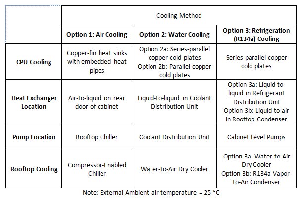
In this article, three cooling solutions summarized in Table 1 , are assessed to provide cooling to a hypothetical, near-future computing cluster. Cooling Option 1 is an air-cooled system with large, high-efficiency, turbine-blade fans pushing air through finned, heat-pipe equipped, copper heat sinks on the blade. Rear-door air-to-liquid heat exchangers on each cabinet cool the exiting air back to room temperature so that no additional air conditioning strain is placed on facility air handlers. The water & propylene glycol (water/PG) mixture from the heat exchangers is pumped to the roof of the facility, where the heat absorbed from the CPUs is dissipated to the environment via a rooftop compressor-enabled chiller.
Cooling Option 2 uses water-based touch cooling on the CPUs via a copper coldplate loop on each board. These loops are connected to an in-rack manifold that feeds a water/PG mixture in and out of each blade. A coolant distribution unit (CDU) collects heated water via overhead manifolds from each cabinet, cools the water through an internal liquid-to-liquid brazed-plate heat exchanger, and pumps it back through the overhead manifolds to the cabinets for re-circulation. On the other side of the heat exchanger, a closed water loop runs from the CDU to a rooftop dry cooler, where the heat from the CPUs is ultimately dissipated into the atmosphere.
Cooling Option 3, which considers two approaches, removes water from the server cabinets and instead uses refrigerant (R134a) as the heat transfer fluid in the server room. This approach uses a coldplate and manifold system similar to the water-cooling approach, but may or may not have a refrigerant distribution unit in the building. Cooling Option 3a pumps mounted in the cabinets pump the refrigerant through a water-cooled, brazed-plate heat exchanger in a refrigerant distribution unit (RDU) to condense the refrigerant after it absorbs the heat from the CPUs. In Cooling Option 3b, pumps move the refrigerant straight to the roof, where a rooftop condenser dissipates the heat to the environment.
Table 1 – Overview of cooling options
The goal of this article is to provide an “apples-to-apples” comparison of these three cooling systems by suggesting a hypothetical, high-power near-future data center specification for each method to cool. When the options are compared side-by side, differences in fluid dynamics and heat transfer will translate into differences in efficiency, and comparisons between various cooling methods become more easily visible. This article is not a complete guide to installing or selecting equipment for each of these cooling systems, but it is a general overview of what power usage advantages each system offers.
Hypothetical Computer Cluster Specification And Thermal Assessment
In order to bound the comparison in a meaningful way, a set of specifications was developed from extensive discussions with the Liquid Cooling (LC) forum of LinkedIn professional network [4], an association of motivated multidisciplinary professionals from HPC, Telecom and electronics cooling industries.
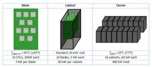
After several weeks of discussion, the LC forum agreed on the following system configuration and operation conditions for analysis: the hypothetical computer cluster under consideration should produce ~1MW of IT power. The distribution of power is shown in Figure 1.
Figure 1 – Hypothetical data center module specifications
The cabinet architecture in this specification assumes horizontal card inserted from the front, with no cards inserted from the back of the cabinet. Alternative architectures exist, and can be cooled by a variety of means, but for this analysis, a simple, easily-relatable architecture was desired, so only front-facing, horizontal cards were considered.
A hypothetical data center could be equipped either with a dry cooler or compressor equipped chiller located on the roof of the building, at up to 60 m (»200 feet) above computer HPC cluster level floor. To maintain the 65°C case temperature limit, the air-cooling method requires a compressor-equipped chiller, but a dry cooler is preferred for liquid cooling methods.
One of the most important requirements for this analysis was its full transparency, so anybody could have a closer look, if desired. When the study results were presented to LC forum participants at a webinar in February, 2015, a number of forum participants requested and (later) participated in a “deeper dive”, so a step-by-step process with a higher level of detail was provided on request. This article is a deeper look at the material presented in the June, 2015 edition of the Electronics Cooling magazine. Justifications for operating points and performance estimates are presented so that readers may see the methodology behind the estimates. Because the comparisons presented in this article are not between measurements of actual, installed systems, it is important to know the details of the hypothetical systems and how their performances are estimated.
COOLING OPTIONS VIEWED VIA EXPLICIT COMPARISON
Option 1: Advanced Air Cooling
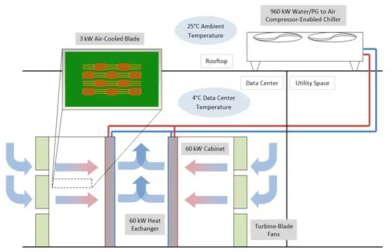
Cooling 60 kW in a single rack requires a staggered, heatsinked 10-CPU layout, heat pipes, rear door cooling heat exchangers, and powerful, high-pressure turbine-blade fans. In addition, the air in the data center still needs to be significantly lower than room temperature (4°C) to achieve the desired case temperature. Even though air cooling may not be an economically feasible solution at this power density, and even though it would not meet the NEBS GR-63 acoustic noise level standard [5], an air cooling option is needed to compare to the LC options.
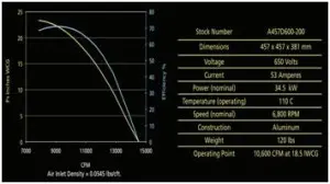
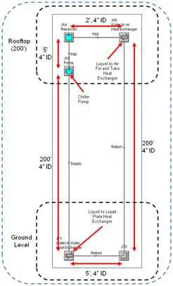
In this approach, each cabinet is supplied with a rear-door cold water/PG cooler with 3 “hurricane” turbine-blade fans (with operating point of ~3.7 m3/s at ~3.7 kPa pressure difference; see Figure 8 [6]). The cold water/PG solution circulates around the system to the roof chiller, where heat from the cabinets is dissipated to the ambient air. The system would be monitored with on-board temperature sensors and would either increase the fan speed or throttle CPU performance if the CPU approached the 65°C case temperature threshold. This approach is illustrated in Figure 2.
Figure 2 – Option 1: Air cooling with rear-door water/PG to air heat exchangers
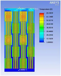
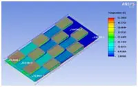
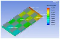
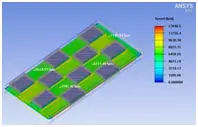
To maintain a 65°C case temperature under the copper-fin heat sinks when the CPU was creating 300W of heat, CFD analysis shows that the cold air must flow through the blade at a speed of 7,000 feet per minute (very fast relative to normal fan air speeds), and must start at 4°C at the inlet (very cold relative to normal server operating conditions). This results in a 14 inches of water column pressure that the fans need to provide.
Figure 3 – CFD analysis of heat sink temperatures
Figure 4 – CFD analysis of air temperature through 10 heat sinks
Figure 5 – CFD analysis of air pressure through 10 heat sinks
Figure 6 – CFD analysis of air flow velocity through 10 heat sinks
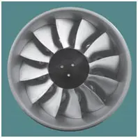
In order to push this much air through the heat sinks at such a large pressure difference, high-efficiency, turbine-blade fans are required. Below are the specifications for the model selected for this application.
Figure 7 – High-pressure, turbine-blade, axial “Hurricane” fan
Figure 8 – Performance specifications for “Hurricane” fan
When the performance of this fan is extrapolated to the entire group of cabinets, the total power consumed by fans alone is about 365 kW, or about 38% of the IT power of the hypothetical cluster. This does not include losses related to power conversion in order to supply the required voltage to the fan.
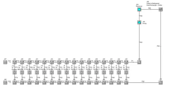
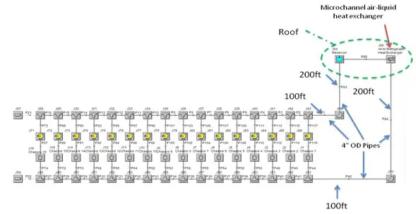
Two other main contributors to the power bill for this approach are the chilled water pump and the rooftop chiller. Below is a screenshot of a flow network analysis model of the chilled water loop, complete with heat exchangers on each cabinet and an air-to-water heat exchanger on the roof.
Figure 9 – Flow network model of rear-door heat exchangers
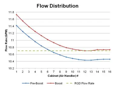
When 16 cabinets are connected in parallel, small imbalances in flow distribution develop because of the small pressure differences from one end of the manifold to the other. To ensure that no cabinet receives a flow rate that is too low to cool the required power, the nominal flow rate is increased by 2.5%. This way, although some cabinets will receive more than enough flow, no cabinet will receive less than the required amount. Below is a graph showing the flow distribution through the 16 cabinets, for both the nominal and “boosted” flow rates.
Figure 10 – Flow distribution through 16 cabinets
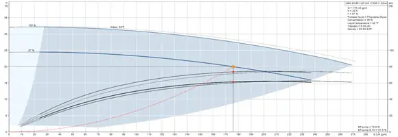
To determine the power required to pump the water/PG through the cabinets, the operating point of the pump must be found by intersecting the pump curve with the system impedance curve. This is where the pressure created by the pump matches the pressure lost as the water/PG flows through the system (or when both the pump and the system are operating stably).
Figure 11 – Operating point for water pump in Option 1
For this system, the operating point is about 175 gallons per minute at 8.8 psi difference across the pump. If the efficiency of the pump is 70%, as catalogue data suggests, then the pump consumes just under 1 kW of power.
The compressor-enabled chiller on the roof serves as the final stage of dissipating the heat from the cabinets. When the refrigerant in the compressor loop is compressed, its temperature rises above ambient, allowing heat to flow from the refrigerant to ambient air as it passes through a heat exchanger. Then the refrigerant is expanded, and dramatically drops in temperature before entering another heat exchanger. As the warm water/PG mixture from the cabinets is pumped through this heat exchanger, the now-cold refrigerant in the chiller cools the water/PG down to sub-ambient temperatures so that it can be pumped back to the cabinets.
Similar chillers have peak efficiencies equal to a power consumption of about .8 kW for every 1 refrigerant ton of cooling, corresponding to an efficiency of about 77%. For the 960 kW heat load on this system, a chiller like this would require 218 kW of power. This estimate differs from other estimates in this study because it estimates the complete power usage, including the power supplies required to run the compressor and fans. In contrast, the other cooling methods do not account for power supplies, and instead calculate the pump and fan power required to achieve a certain cooling capacity, assuming a typical fan and pump efficiency.
Option 2: Water/PG Touch Cooling
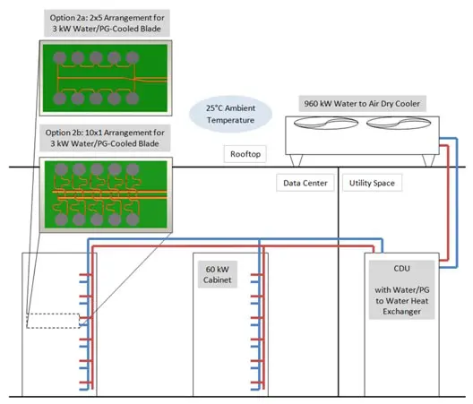
In Option 2a , (Figure 12, top board layout) 10 CPUs per blade are arranged in two parallel groups of 5 serially connected cold plates (Option 2a). 20 horizontal blades are plugged into vertical supply/return manifolds, and these cabinet manifolds are supplied with water/PG from the Coolant Distribution Unit (CDU) via overhead manifolds. In the CDU, a brazed-plate heat exchanger transfers heat from the cabinet loop to a separate loop that brings the warm water to a rooftop dry cooler unit, where the heat is rejected into the ambient air. This method would include a control system in the CDU that would increase the water flow rate in the case of an increased load. Either passive or active flow regulators would also be placed at the inlet of each blade to ensure even flow distribution across the whole cabinet.
After the first pass of Water/PG system simulation it was discovered that water/PG speeds in the blade exceeded allowable ASHRAE [1] velocity limits, so an additional LC option (Option 2b) was added – where all 10 cold plates were connected in parallel. This required additional onboard manifolds with additional piping to allow for a compliant cold plate/CPU interface.
Figure 12 – Option 2: Water/PG touch cooling
The coldplates used for Options 2a and 2b are copper skived-fin coldplates, and have a thermal resistance of about .025 °C/W from the coldplate surface to the liquid refrigerant. At this resistance, the coldplates can dissipate the 300 W per chip with only a 7.5°C difference between the coldplate surface and the coolant. This determines the operating point of the rest of the system by placing a limit on how high the water temperature can go before chips begin to exceed their thermal boundaries (65°C maximum case temperature).
The flow rate through the blade required to cool five coldplates in series with water/PG mixture entering at 45°C is about .985 gallons per minute, so a blade with 10 CPUs (2 parallel lines of 5 coldplates each) would require 1.97 gallons per minute.
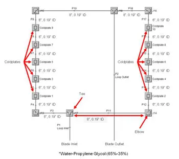
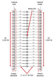
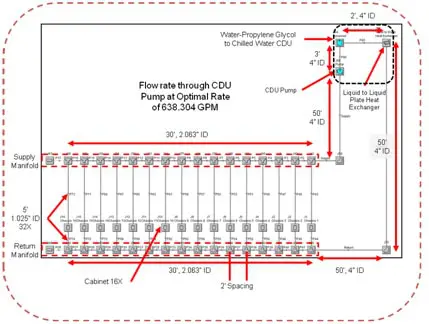
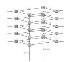
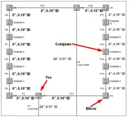
Flow network analysis was used to determine the pressure drop of the blade-level serial-parallel network and at the cabinet level with 20 blades. Then the entire 16-cabinet cluster was modeled to obtain system pressure drops to aid in determining the operating cost of the system.
Figure 13 – Flow network analysis model for blade in Option 2a
Figure 14 – Flow network analysis model for cabinet in Options 2a & 2b
Figure 15 – Flow network analysis model for cluster in Options 2a & 2b
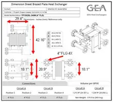
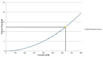
The flat plate heat exchangers used in Options 2a and 2b account for a substantial portion of the total pressure drop as the water is pumped around the loops, both in the loop that connects the cabinet to the CDU and the loop that connects the CDU to the rooftop dry cooler. Data from the manufacturer was used to estimate this pressure drop, and is based on the manufacturer’s empirical data.
Figure 16 – Flat plate heat exchanger used in Options 2a & 2b
Figure 17 – Flow curve for flat plate heat exchanger
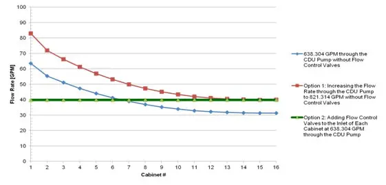
The same flow distribution issue that exists in Option 1 also exists here. The distribution of flow through the cabinets is such that the entire flow rate needs to be “boosted” in order to avoid any cabinet receiving less than enough water/PG mixture. However, this boost is much more costly in this case because the pressure drops between cabinets are much greater due to larger flow rates. This means that the difference between the first and last cabinet will experience a large difference in flow rate, so large that the first cabinet receives more than twice the required flow rate. To avoid pumping more fluid than is necessary, flow control valves can be added at the inlet of each cabinet to throttle the flow, so that each cabinet receives a uniform flow rate. This will equalize the flow rate across the entire system, but will increase the total pressure drop due to the increased impedance of partially throttled cabinets.
Figure 18 – Comparison of flow rates across 16 cabinets in three scenarios: “un-boosted,” “boosted,” and with flow control valves
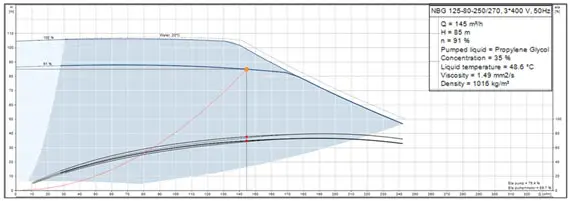
The total flow rate for 16 cabinets is 638 gallons per minute at 123 psi across the pump. At this flow rate, the efficiency of the pump is about 74.5%, meaning that the pump will require 45.7 kW to provide this flow rate and pressure.
Figure 19 – Operating point for water pump in Option 2a
From the heat exchanger in the CDU, another water loop takes water to the roof to dissipate the heat to the outside air via a rooftop dry cooler. The chiller pump in this loop pumps 305 gallons per minute at a pressure difference of 20 psi, resulting in another 3.10 kW of power for the system. The layout of this loop is shown in Figure 20.
Figure 20 – Flow network analysis model of water loop in Options 2a & 2b
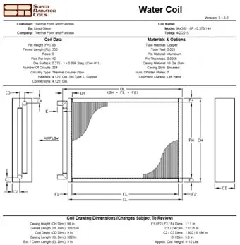
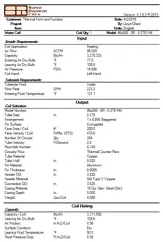
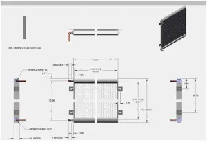
The last component of the heat tranfer system is the heat exchanger that dissipates the heat to the atmosphere. A tube-and-fin heat exchanger is used because of its scaleability; other heat exchangers, such as aluminum microchannels, have large pressure drops as their size increases, but tube-and-fins can retain a low pressure drop even at large scales. This heat exchanger occupies approximately the same size footprint on the roof as the cabinets take up in the computing space. Depending on how expensive rooftop real estate is compared to indoor real estate will determine if this condenser will be resized in an actual installation, but this design is fairly economical considering the large power that it is dissipating. This is also the same heat exchanger that is used in Option 1 and Option 3a.
Figure 21 – Water to air heat exchanger specifications
Figure 22 – Water to air heat exchanger performance estimates
The flow rate through the blade in Option 2a with standard 1/4″ copper tubing exceeds the velocity recommended by ASHRAE for water systems. Erosion of the copper tubing is likely to occur in these systems, which could result in early leakage or unpredictable flow changes. To avoid this problem, the blade-level distribution can be reorganized so that the coldplates are all connected in parallel, rather than having five coldplates in series. This change in coldplate layout constitutes Option 2b.
Figure 23 – Flow network analysis model of parallel coldplate loop in Option 2b
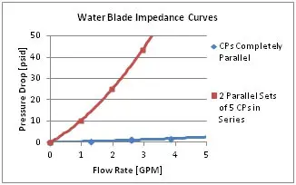
Figure 24 – Comparison of flow curves for coldplate loops in Options 2a and 2b
With the substantially reduced pressure drop across the cabinet cooling loop (20 psi vs. 123 psi), Option 2b uses 9.75 kW of power to pump the water/PG mixture, almost five times less than Option 2a. In total, when considering both pumps and the fans of the dry cooler, Option 2b requires about half the power as Option 2a, but will require more copper tubing space on the board to accomplish the completely parallel routing.
Option 3: R134a Touch Cooling
The high heat of vaporization for refrigerant enables refrigerant systems to use a flow rate that is approximately 5 times less than the required flow rate for a water system with the same power. Because of this, the cold plates in Option 3 do not need to be connected in parallel like in Option 2b, and can have an arrangement similar to Option 2a. As before, blades are connected to vertical supply/return (refrigerant) manifolds, but because of the lower flow rate, a refrigerant pump can be fit into each cabinet to pump refrigerant through the blades and manifolds.
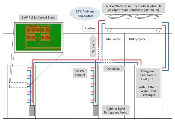
In option 3a, the manifolds transport the refrigerant to a refrigerant distribution unit (RDU), where the heat is transferred to a closed water loop feeding into a rooftop dry cooler. In option 3b, the refrigerant is sent straight to the roof, where a rooftop condenser dissipates the heat to the atmosphere. The layouts of these two options are shown schematically in Figure 25.
The control system for a refrigerant cooling system includes a built-in headroom for the refrigerant capacity. The system is designed so that under a full load, the refrigerant quality (the fraction of refrigerant that is vapor, by mass) does not exceed 80%, so a 20% safety factor is already built into the system at the worst-case scenario. Flow regulators at the inlet of each blade ensure even flow distribution across the entire height of the cabinet. In the event of an increase in CPU power, either the RDU would increase the water flow rate or the rooftop condenser would increase its fan speed to fully condense the refrigerant.
Figure 25 – Option 3: R134a touch cooling
One advantage with refrigerant that becomes clearly visible is the difference in flow rate required for a given power between refrigerant and water systems. The phase change of refrigerant from liquid at 25°C to vapor at 25°C requires the same amount of heat per unit mass as heating water from 25°C to 67°C. However, the phase change does create a higher pressure drop than single-phase flow does for a given flow rate.
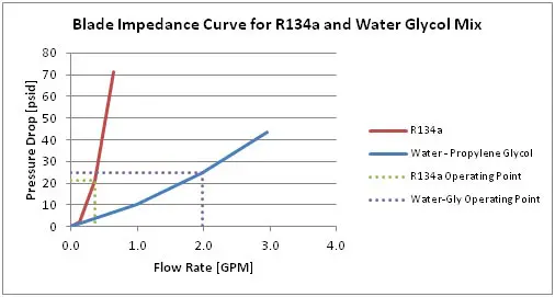
Figure 26 shows the correlation between pressure and flow rate for a refrigerant and a water/PG loop. The operating points on each graph show where each system would fall while cooling 3 kW on the hypothetical blade.
Figure 26 – Comparison of operating points for a water-cooled vs. R134a-cooled system
The blade was modeled using flow analysis software to determine the pressure drop across the blade based on the required flow rate for 3 kW power. This arrangement was then simplified to a single component in the software so that the entire cabinet could be modeled, complete with quick disconnects and flow regulators at the inlet of each blade.
Figure 27 – Flow network analysis model of coldplate loop in Options 3a & 3b
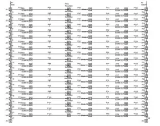
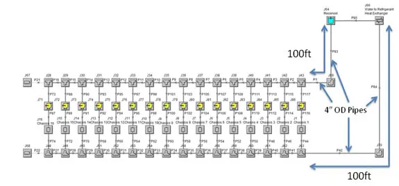
Figure 28 – Flow network analysis model of 20-blade cabinet in Options 3a & 3b
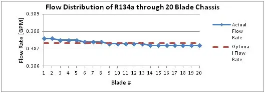
With the in-line flow regulators in each blade, the flow rate through the cabinet is very even. Only a small variation in flow rate can be seen from the first blade to the last blade. The advantages of using flow regulators (simplicity of the control system and accuracy of flow distribution) generally outweigh the cost of a slightly increased pressure drop, but it is possible to design a system without flow regulators. For this study, the simplest method was preferred, so flow regulators are used on the blades.
Figure 29 – Flow distribution through cabinet in Options 3a & 3b
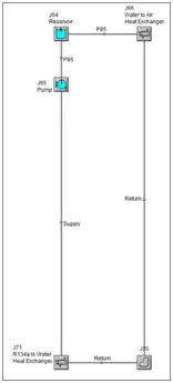
Figure 30 – Flow network analysis model of cabinet loop in Option 3a
At the cluster scale, the power required by the system is determined by the cabinet-level pumps in the cabinet-to-CDU loop, as well as the pump and the fans in the dry cooler loop. Because experimental data is scarce for such a large flow rate, the empiric two phase correlations were used to estimate the pressure drop based on the analysis of single-phase flow. The flow through the blade and CDU loop, complete with a heat exchanger, came out to about 7.24 gallons per minute per pump, at a pressure difference of about 41 psi. Using the two-phase correlation to estimate the additional pressure drop for the piping carrying an 80% quality mixture yields an additional pressure drop of about 5 psi, for a total of about 46 psi across the pump. At an efficiency of 30% (typical for positive displacement pumps) the pumps would require about 480 watts each, for a total of 7.76 kW in the 16 cabinet cluster.
A second loop carries water from the CDU to the roof, where a dry cooler expels the heat to the atmosphere. This dry cooler uses the same liquid-to-air heat exchanger that the previous options use, so the flow rates and pressure drops are similar as well.
Figure 31 – Flow network analysis model of water loop in Option 3a
Figure 32 – Flow network analysis model of R134a loop in Option 3b
Figure 33 – Aluminum microchannel used in Option 3b
In Option 3b, there is only one coolant loop to consider, containing the coldplate loops, the cabinet-level pumps, and the rooftop condenser. The Gronnerud correlation was again used to estimate the pressure drop across the system. 15 psi was added to the single phase pressure drop of 54 psi to reach a total pressure drop of 69 psi at 7.24 gallons per minute per pump. At 30% efficiency, this requires about 11.6 kW of power. The total power for 3a and 3b is tabulated in the following section.
Because the direct refrigerant option (Option 3b) maintains a higher approach temperature at the roof, a deep tube-and-fin condenser is not necessary and a more cost-effective aluminum microchannel condenser can do the same job with a smaller form factor and lower cost. Also, because the refrigerant flows directly to the roof (and there are fewer thermal losses on the coolant’s path to the atmosphere), the approach temperature at the rooftop condenser is greater than the approach temperature in any of the other cooling options, which results in a lower fan speed and lower power consumption at the rooftop.
Capital and Operating Expenditures
With identical performance specifications (maximum case temperature and environmental ambient temperature), the differences between cooling systems can be easily compared in terms of capital and operating expenses (CapEx and OpEx, respectively).
It is important to mention that the presented first-pass analysis was not intended to produce entirely optimal designs for each cooling option. For equipment selection, computational fluid dynamics (CFD) analysis [7], flow network analysis [8], a two-phase analysis software suite, and vendors’ product selection software [9, 10] were used to analyze pressure drops and heat transfer across different system components.
For each cooling option, capital expenses were determined by obtaining quotes of only the main components of cooling hardware (fans, heat exchangers, pumps, coldplates, refrigerant quick disconnects, etc.) from the manufacturer, and 10% of the cost was assessed for installation, piping, etc. The cost for the electric power supply, controls, hose and pipe fittings, UPS, etc. was not included. This cost is certainly an underestimate of the total cost of installation, but it would be representative of the main cost drivers associated with each cooling system.
One important note about the CapEx estimates is that the water and refrigerant coldplates are assumed to be of equal cost. In reality, water coldplates require higher flow rates and therefore larger tube diameters to cool the same power, but refrigerant coldplates must withstand higher pressures. The actual cost of manufacturing depends more on the manufacturing technique than it does on the fluid used, so the two coldplates were assumed to be of similar cost.
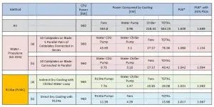
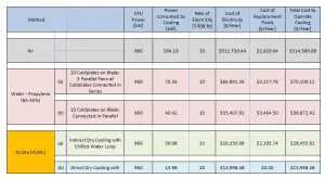
Major sources of power consumption and OpEx for all three methods are shown in Tables 2 and 3.
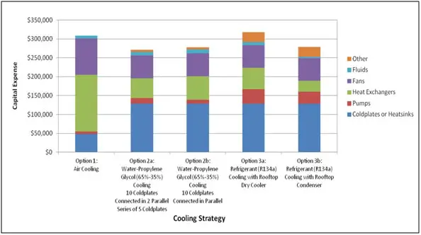
Figure 34 – Capital expenses for five cooling strategies
Operating expenses for all cases were calculated by determining the cost of electricity needed to pump the coolant around the loop and to run the fans. To do this, Computational Fluid Dynamics (CFD) and flow network analysis were used to calculate the pressure drop and flow rate of each fluid through the system, and then an average operational efficiency was used to determine the total power draw. This analysis used $0.10 / kW-hr, without demand charges, and operating hours per year were 8,760 for all methods.
Since the refrigerant-based option does not require periodic flushing and replacement, in this analysis the cost of R134a was only added to CapEx. With water cooling, in order to keep electro galvanic corrosion inhibitors and microbiological growth suppressants active, water/PG Coolant mixture requires regular (every 2-3 years) flushing, so the cost of water cooling additives was added to OpEx as well as the initial CapEx estimate.
Table 2 – Major sources of power consumption for cooling options
Table 3 – Operating costs for cooling options
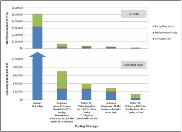
Figure 35 – Operating expenses for five cooling strategies
Figure 35 shows that using a direct, rear-door air-cooling approach, low data center temperature, heat sinks with embedded heat pipes, and turbine-blade high-efficiency fans, air cooling will cost far more than a liquid-cooling option. Again, this best effort for air cooling option was presented only for the sake of comparison.
Figure 35 also indicates that that switching from air-cooling to any of the four liquid-cooling options will cut the operating expense (to run the cooling system, not to run the entire data center) by at least a factor of 5, In addition, the direct refrigerant cooling option (Option 3b) shows the lowest operating cost of all the cooling options, with less than 1/30th of the cost of the air-cooled option (Option 1). With this operating cost, an existing air-cooled data center (per Option 1) would greatly benefit from switching to a refrigerant-cooled data center (Option 3b), and, assuming no additional retrofit expenses, would recover the switching cost within the first year of operation.
CONCLUSION
Although the comparison in this paper is a preliminary, predictive analysis of several different cooling systems, the differences in power consumption revealed here show that a data center outfitted with liquid cooling provides a tremendous advantage over air cooling at the specified power level (60 kW per cabinet). As HPC and Telecom equipment continues toward higher power densities, the inevitable shift to liquid cooling will force designers to choose between water and refrigerant cooling. It is the author’s belief that the industry will eventually choose direct refrigerant cooling because of the advantage it has over other cooling systems in operating cost (at least 2.5 times cheaper) with similar capital cost, the minimal space requirements on the board, the absence of microbiological growth, galvanic corrosion and the corresponding need to periodically flush the system, as well as the fact that conductive leaks are nonexistent.
ACKNOWLEDGEMENTS
This study was inspired, promoted, and scrutinized by dedicated professionals representing all cooling approaches, from the Liquid Cooling forum at LinkedIn, and carried out by Thermal Form & Function, Inc.
REFERENCES
[1] ASHRAE TC 9.9 2011 “Thermal Guidelines for Liquid Cooled Data Processing Environments”, 2011 American Society of Heating, Refrigerating and Air-Conditioning Engineers, Inc.
[2] Brock, David. Understanding Moore’s Law: Four Decades of Innovation (PDF). Chemical Heritage Foundation. pp. 67–84. ISBN 0-941901-41-6. http://www.chemheritage.org/community/store/books-and-catalogs/understanding-moores-law.aspx, Retrieved March 15, 2015.
[3] Hannemann, R., and Chu, H., Analysis of Alternative Data Center Cooling Approaches, InterPACK ‘07 July 8-12, 2007 Vancouver, BC, Canada, Paper No.
IPACK2007-33176, pp. 743-750.
[4] LinkedIn Liquid Cooling Forum. https://www.linkedin.com/grp/post/2265768-5924941519957037060, Retrieved May 11, 2015.
[5] Network Equipment-Building System (NEBS) Requirements: Physical Protection(A Module of LSSGR, FR-64; TSGR, FR-440; and NEBSFR, FR-2063). NEBS Requirements: Physical Protection GR–63–CORE, Issue 1, October 1995
[6] Xcelaero Corporation, “Hurricane 200,” A457D600-200 datasheet, 2010. http://www.xcelaero.com/content/documents/hurricane-brochure_r5.indd.pdf, Retrieved May 11, 2015.
[7] ANSYS Icepak. Ver. 16. Computer Software. Ansys, Inc., 2015.
[8] AFT Fathom. Ver. 7.0. Computer Software. Applied Flow Technology, 2011.
[9] LuvataSelect. Ver. 2.00.48. Computer Software. Luvata, 2015. http://www.luvataselectna.com, Retrieved May 11, 2015.
[10] Enterprise Coil Selection Program. Ver. 3.1.6.0. Computer Software. Super Radiator Coils, 2015. http://www.srcoils.com/resources-support/coil-sizing-software/, Retrieved May 11, 2015.

