By: Yong Quiang Chi, Peter Hopton and Keith Deakin, Iceotope Ltd
Jonathan Summers, Alan Real, Nik Kapur and Harvey Thompson, University of Leeds
Introduction
Improvements in energy efficiency and performance of data centers are possible when liquid is supplied to the racks [1]. A solution which has become popular for dense racks is the rear-door water-cooled heat exchangers (RDHx) [2]. Moving liquid to the rack reduces the traveling distance of conditioned air, however, RDHx solutions rely on air-cooled design datacom components and is classified as indirect liquid cooling (ILC).
There are a growing number of suppliers that provide liquid-cooled solutions, where the liquid directly cools the datacom equipment, classified as direct liquid cooling (DLC) [3]. A subset of these does not require any form of supplementary cooling via air and are classified as total liquid cooling (TLC), which rely on the use of non-conducting (dielectric) liquids that are either pumped [4], rely on phase change [5] or make use of natural liquid convection [6].
Method of comparing ILC and TLC
The configuration and experimental data for the comparison of the two cooling approaches is acquired from two operational systems and the collected data is applied to construct two design systems for comparison of ILC and TLC, where the IT is exactly the same. A single 2U rack chassis node with a single motherboard converted from one of the fully immersed liquid-cooled systems was employed for comparison of the two cooling methodologies. The only physical difference between the 2 systems is in the rack level cooling methods, that being ILC and TLC.
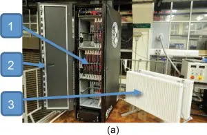
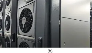
The enclosed, immersed, TLC system was deployed in a laboratory environment as shown in Figure 1(a), where the TLC modules (1), rack (2) and radiators heated by return water from the TLC modules (3) are indicated. Datacom performance, PDU power measurements, and temperatures obtained from this system are used for the analysis of the rack level performance and power consumption. The cooling configuration of the ILC High-Performance Computing (HPC) system (see Figure 1(b)) uses fan-assisted rear door liquid-loop heat exchangers connected to 500kW of external chillers, which has provided power and cooling data for the comparison.
Figure 1(a) Rack with integrated TLC modules with (1) TLC modules, (2) rack, and (3) radiators [7]
Figure1(b) – part of the data center HPC system showing the fan-assisted rear door liquid-loop heat exchangers.
The IT, rack, and data center power and thermal data acquired from both real systems is used to construct the design systems with identical IT hardware, but comparing the performance of the two different cooling strategies. The same server level motherboard and CPU arrangement (namely SuperMicro X9D with Intel dual 2670 Xeons) and the Airedale Ultima Compact FreeCool chillers for the final heat removal step are included to complete the total energy calculation. Power consumption measurements were performed with (i) the rack of TLC modules, and (ii) a single node of the total liquid-cooled system was removed from its enclosure and run in a single air-cooled rack configuration to conduct the same power consumption measurements, but cooled by air and fans rather than the dielectric liquid. The results from these 2 tests provide the basic thermal and power consumption data to build up the design based total liquid-cooled and indirect liquid-cooled data centers.
Determine rack-level temperatures and data center residual heat.
Constructing a data center design based on TLC requires experimental data on the supply and return water temperatures to the racks and the residual heat emitted to the data center. In [9] calculations for the small TLC system in Figure 1(a) demonstrated that for a consumption of 2128W, 1367W of thermal power would enter the surroundings from the rack at a supply and return water temperature of 32oC and 38oC respectively. Baying racks together would reduce the exposed rack surface area so the thermal losses are expected to be smaller than the value obtained from the experimental system, but for a fully loaded 48 server rack it is assumed that less than 10% of thermal energy will be lost to the data center, which is based on the fact that the system power consumption will increase but the surface area for heat loss remains constant.
For the ILC system, temperatures and residual heat can be obtained from a single air-cooled computer node. An experiment was set up to monitor the inlet and outlet temperatures, together with the airflow rate to obtain typical temperature increases over the inlet temperature for the main server components. To capture a realistic outflow temperature, the outlet air was funneled into an insulated duct with an exhaust diameter of 75mm and a length of 400mm. This was found sufficient to characterize the outlet temperature from a single measurement. The mean velocity was calculated by taking a series of measurements across the pipe diameter, and thus calculating the mean airflow.
The server-level tests made use of two software tools to produce a near 100% load on the server, namely StressLinux [10] and High-Performance Linpack [11]. This resulted in a total energy load reading of 305W, which does not include the server fans as these are powered externally.
Temperature and velocity readings were taken at a range of points over the diameter of the exhaust pipe and all readings became repeatedly stable after 2 hours of continuous running. After several runs the temperature delta from the inlet to the outlet was 12.54oC. Under the measured exhaust conditions of 37oC, the air density, ρ, is approximately 1.138kg/m3 and the mass flow rate, ṁ, of the outlet can be calculated as,
where A is the surface area of the ducted outlet, 0.004418m2, and is the averaged air velocity of the outlet, 4.45 m/s, which results in the mass flow rate is ṁ=0.02237kg/s.
The average specific heat capacity (SHC) of air between inlet at 25oC and outlet at 37oC is approximately 1005 J/(kg·oC), and since the temperature difference from the inlet to outlet, ∆T, was measured to be 12.54oC, the total heat flux Q that is released into the air would be,
In [2], the fan assistant RDHx units were found to be able to remove almost 94% of the heat, but when combined with the thermal losses in the server this would drop to 87% of the heat being removed. Therefore, as with the TLC solutions based on liquid immersed servers, there will be a requirement for CRAH units to handle a maximum of 10% of both TLC and ILC system thermal loads.
Operations of the design data center
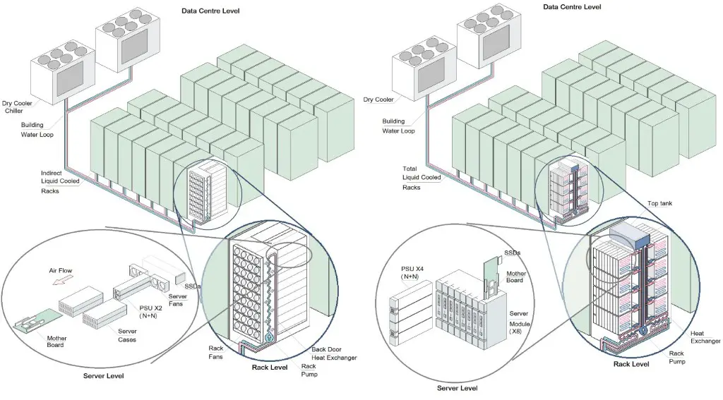
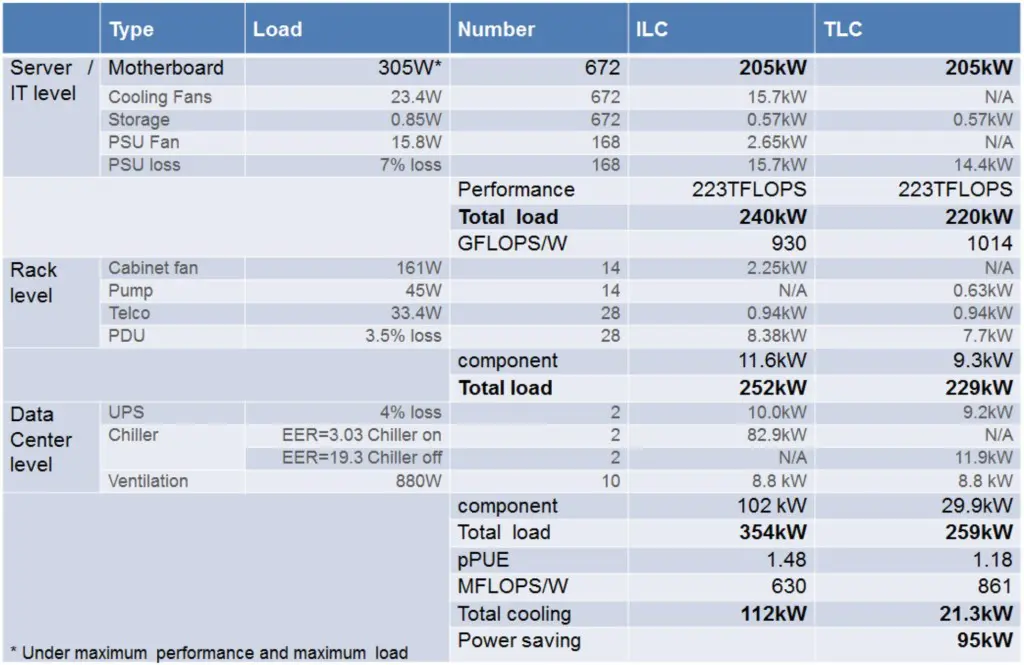
The design data center using the two rack-level cooling configurations are shown in Figure 2. The full sets of calculated results are detailed in Table 1 for a target of 250kW of total power consumption for both ILC and TLC based solutions.
Figure 2 Schematics showing ILC (left) and TLC (right) system levels of the data center.
Table 1 Overall power data of an ILC based data center compared to one with TLC server technology.
From Table 1 it can be seen that the TLC based solution is able to achieve a partial Power Usage Effectiveness (pPUE) of approximately 1.18 at full load, which means that 0.18kW of power is required to cool 1kW of operating IT. This is compared to an equivalent ILC based system, which has a pPUE of 1.48. However this is based on the assumption that the computer systems are fully loaded and that the outside ambient air temperature was 25 oC, as shown in Table 2, then for the ILC systems require mechanical cooling, which is a worst-case cooling scenario for ILC.
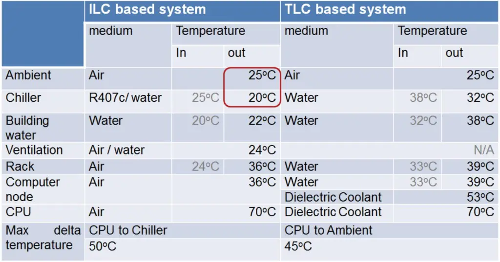
Table 2 Measured temperatures of the components for the comparison of ILC and TLC based data centers.
Chillers usually have an Energy Efficiency Ratio (EER) of around 3.0, indicating that 3.0kW of cooling can be provided by 1kW of power, under fully loaded conditions, which results in the pPUE of the data center that is at least 1.33 when the chiller is operating at 100% mechanical load.
It is also possible to directly compare the data center level Performance Per Watt (PPW) of these 2 hypothetical systems since they contain identical computing hardware. From Table 1, the ILC system is rated to 632 MFLOPS/W, while the TLC system is rated at 858 MFLOPS/W.
From Table 2 it can also be seen that the ILC solution has a supply and return temperature that is lower than ambient whereas the TLC solution has supply and return temperatures greater than ambient, which is the reason why the chillers would be operating in mechanical cooling mode to deal with the additional cooling requirements.
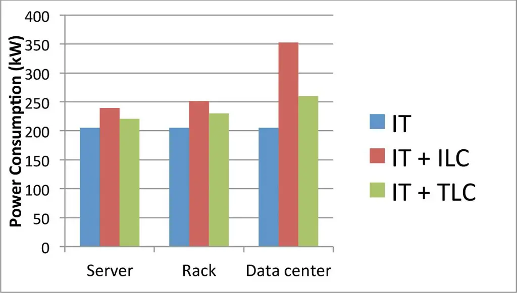
The key results of Table 1 can be seen quite easily in Figure 3, which demonstrates the larger cooling overhead for ILC compared to TLC at the different levels, which are depicted in Figure 2.
Figure 3 Histogram of power consumed by ILC and TLC at the various levels within the data center.
Conclusion
A data center based on ILC systems is calculated to operate with a partial PUE of 1.48. This is compared with a TLC based data centre, which is calculated to operate at a partial PUE of 1.18 – 63% more effective at heat removal. Comparing performance yields a value for the ILC system of 630MFLOPS/W, which can be compared to the TLC based system of 861MFLOPS/W – 37% better performance. Finally the data centre based on TLC systems, under 25oC ambient air conditions, consumes 95kW less power, which saves 27% of the total power and more than 81% of cooling power over the ILC based system.
Acknowledgments
The authors are grateful for the financial support from Iceotope Ltd and the University of Leeds’ Digital Innovation Research Hub.
References
- Iyengar, Madhusudan, et al. “Server liquid cooling with chiller-less data center design to enable significant energy savings.” Semiconductor Thermal Measurement and Management Symposium (SEMI-THERM), 2012 28th Annual IEEE. IEEE, 2012
- Almoli, Ali, et al. “Computational fluid dynamic investigation of liquid rack cooling in data centres.” Applied Energy1 pp150-155, 2012
- 451 Research. “Liquid-Cooled IT: A flood of disruption for the datacentre”, July 2014
- Attlesey, Chad Daniel. “Case and rack system for liquid submersion cooling of electronic devices connected in an array.” U.S. Patent No. 7,905,106. 15 Mar. 2011.
- Tuma, Phillip E. “The merits of open bath immersion cooling of datacom equipment.” Semiconductor Thermal Measurement and Management Symposium, 2010. SEMI-THERM 2010. 26th Annual IEEE. IEEE, 2010
- Hopton, Peter, and Jonathan Summers. “Enclosed Liquid Natural Convection as a Means of Transferring Heat from Microelectronics to Cold Plates.” Semiconductor Thermal Measurement and Management Symposium, 2013. SEMI-THERM 2013. 29th Annual IEEE. IEEE, 2013
- Airedale, University of Leeds Case Study , High density IT cooling, Airedale, 2012.
Available from http://www.airedale.com/web/file?uuid=0fd59a99-917c-4363-9926-10a314de648c&owner=de3aa83e-cfaf-4872-8849-d5a40ddcd334&contentid=2027&name=University+of+Leeds+Case+Study.pdf
- Yong Quiang Chi, et al. “Case study if a data centre using enclosed, immersed, direct liquid-cooled servers.” Semiconductor Thermal Measurement and Management Symposium, 2014. SEMI-THERM 2014. 30th Annual IEEE. IEEE, 2014

