By Satish G. Kandlikar1,2 and Arvind Jaikumar2
1Mechanical Engineering Department, Rochester Institute of Technology, 76 Lomb Memorial Dr., Rochester, NY 14623, USA; 2Microsystems Engineering Department, Rochester Institute of Technology, 168 Lomb Memorial Dr., Rochester, NY 14623, USA
The advancements in microelectronics and micro-electro-mechanical systems (MEMS) devices to meet the miniaturization trend has placed an increasing demand on thermal management. Single-phase cooling techniques utilize sensible heat transfer mode which is reliable, but is incapable of sustaining the increasing thermal trends as the design is generally pressure drop limited. Furthermore these cooling techniques present large temperature increase in the working fluid that is undesirable. Two-phase cooling offers attractive cooling possibilities by using the latent heat in which the liquid contacting the heated surface changes its state to vapor and removes large amounts of heat. The heat removal process is governed by two performance parameters (i) Critical Heat Flux (CHF) and (ii) Heat Transfer Coefficient (HTC). At CHF, a vapor layer encapsulates the surface preventing the liquid from contacting the surface and significantly hampering the heat transfer. In other words, the CHF is the upper governing limit of the efficient heat dissipating regime in the boiling mode. On the other hand, the temperature difference needs to be maintained at a minimum which dictates the efficiency of the heat removal process. Equation (1) gives the relationship between HTC, heat flux and the temperature difference between the surface (junction) temperature and the saturation temperature of the liquid employed.
(1)
where HTC = heat transfer coefficient (W/m2°C), = heat flux (W/m2),
.
The HTC is inversely related to the temperature difference so a high value is desirable to keep the surface temperatures low. Moreover the convective thermal insulance (Rth) at the interface of the heater surface and the boiling fluid is the inverse of HTC as shown in equation (2):
(2)
where = thermal insulance (m2°C/W).
In the last decade researchers have employed a wide variety of surface enhancements including microgrooves [1], pin fins [2], porous coatings [3], and graphene coatings [4] to reach a CHF of 150 – 200 W/cm2 with water. Area enhancement, availability of additional nucleation sites and liquid wettability changes were identified as the chief contributing enhancement mechanisms. A plain copper surface without any enhancement feature results in a CHF of 128 W/cm2 with distilled water and 11 W/cm2 with FC-87 which is a dielectric fluid. These values are used here to serve as a baseline for enhancement comparisons.
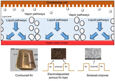
A new class of enhancement technique has been proposed recently [5-7]. Fundamental pool boiling mechanisms suggest that liquid rewetting i.e. liquid supply to the nucleation site after the bubble has departed from the nucleation site is critical in extending the CHF. Kandlikar [5] developed a contoured fin surface in which the bubble motion was governed by evaporation momentum force. In this surface, the nucleation site was formed at the intersection of fin and land. The resulting bubble trajectory was such that it travelled along the contour of the land with subsequent liquid addition through the fin as shown in Figure 1 (lower left image). This technique resulted in a CHF of 300 W/cm2 at a temperature difference of 4.9 °C with an extremely high HTC of 62.9 W/cm2°C. This formed the foundation for the development of surfaces with separate liquid-vapor pathways.

In another configuration which comprised of open microchannels and porous coatings, Patil & Kandlikar [6] used a two-step electrodeposition process to coat the fin tops of open microchannels with copper. The resulting surface had a cauliflower like morphology with the pore size ranging between 5-20 µm as shown in Figure 1 (lower middle image). This influenced the nucleation to occur on the fin tops with subsequent liquid addition through the channels regions similar to a jet impingement like mechanism. This resulted in a CHF of 325 W/cm2 at a temperature difference of 7.3 °C. Jaikumar & Kandlikar [7] investigated three surfaces by using screen printing and sintering on open microchannels and were identified as (i) sintered-throughout (porous coatings completely covering the microchannel geometry), (ii) sintered-channel (porous coatings inside the channel) and (iii) sintered-fin tops (porous coatings on fin tops) respectively. The porous coatings yielded a pore size similar to that of Patil & Kandlikar [6]. While the performance of sintered-throughout surface was enhanced by increased nucleation activity, the sintered-fin-tops and sintered-channels generated separate liquid-vapor pathways. The sintered-channel was capable of sustaining the separate liquid-vapor pathways at higher heat fluxes which resulted in a CHF of 303 W/cm2 and a HTC of 31.5 W/cm2°C with water.
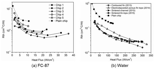
Although water is a popular fluid with good thermal properties it cannot be easily extended to electronics cooling applications due to its conducting nature and high saturation temperature. With a typical temperature limit of 85 °C imposed by the electronics industry, it is important to obtain an experimental database with dielectric fluids (i.e. FC-87, FC-72, HFE, etc.) which are more suited for electronics cooling application. Jaikumar & Kandlikar [8] extended the work conducted by Patil & Kandlikar [6] to FC-87. Figure 2(a) shows the pool boiling curves obtained with the enhanced surfaces. The heat flux is represented in units of W/cm2 which is the desirable units for electronics cooling applications. Chips 1 to 5 have different dimensions which are listed in Table 1. A CHF of 37 W/cm2 was obtained with this surface with a highest HTC of 2 W/cm2°C. Similar liquid-vapor pathways to that observed with water was found. Generation of separate liquid-vapor pathways simultaneously increases the CHF and HTC, and offer a wide operating range by effectively removing heat at small temperature differences compared to its single-phase counterparts.
Table 1. Dimensions of open microchannel geometry used in the study with FC-87 as the boiling liquid.

The performance values indicate that the cohesive effect of channel width and depth dictates the degree of enhancement. The channel width and depth govern the quantity of liquid turning towards the fin tops and the flow resistance the liquid has to overcome to reach the fin tops, respectively. A closer examination revealed that a channel width to depth ratio of unity enhanced the performance significantly which is in complete agreement with the results obtained with water. When this ratio is smaller than unity then the channel depth is more and the liquid will be unable to reach the channel bottoms and turn towards the fin tops; the flow resistance dominates such surfaces and deteriorates the performance. When the ratio exceeds unity the liquid impingement suffers and the reduction in area hampers the performance.
There is a need to further investigate the performance of aforementioned enhancements [5,7] with dielectric fluids. Some of the thermal considerations that make two-phase cooling attractive for high energy density components are: (i) better and efficient cooling performance (ii) a high factor of safety (for reaching CHF) as the vapor chamber offers a wider operating range. As an example, for a 20 W/cm2 thermal load, the vapor chamber performance shown in Figure 2 provides a CHF value of up to 37 W/cm2 thereby giving an extra 30 – 40 % operation range. (iii) The componential cost is also significantly reduced as there is no inclusion of pumps and other flow regulating devices.
Conclusions
The development of enhanced surfaces with separate liquid-vapor pathways has shown immense potential to increase both CHF and HTC simultaneously. Furthermore a distinct advantage of these heat exchangers is that they can be manufactured using conventional milling, computer numerical control (CNC) milling, embossing technique, etc. The porous coatings can be deposited using screen printing, electrodeposition, spray coating, etc. which make it feasible for cooling high heat flux devices. The research presented shows that the separate liquid-vapor pathways can be effectively utilized with water as well as dielectric fluids in enhancing pool boiling heat transfer.
References
[1] Guo, C., Hu, X., Wu, L., Tang, D., and Wang, T., 2009, “Analysis of micro vapor bubble growing process in open capillary microgrooves,” 7th International Conference on Nanochannels, Microchannels, and Minichannels, ICNMM2009, June 22, 2009 – June 24, 2009, American Society of Mechanical Engineers, pp. 595–601.
[2] Pastuszko, R., and Piasecka, M., 2012, “Pool boiling on surfaces with mini-fins and micro-cavities,” 6th Eur. Therm. Sci. Conf. Eurotherm 2012, Conference series 395, p. 012137.
[3] Li, C., and Peterson, G. P., 2007, “Parametric study of pool boiling on horizontal highly conductive microporous coated surfaces,” J. Heat Transf.-Trans. Asme, 129(11), pp. 1465–1475.
[4] Ahn, H. S., Kim, J. M., and Kim, M. H., 2013, “Experimental study of the effect of a reduced graphene oxide coating on critical heat flux enhancement,” Int. J. Heat Mass Transf., 60, pp. 763–771.
[5] Kandlikar, S. G., 2013, “Controlling bubble motion over heated surface through evaporation momentum force to enhance pool boiling heat transfer,” Appl. Phys. Lett., 102(5), p. 051611 (5 pp.).
[6] Patil, C. M., and Kandlikar, S. G., 2014, “Pool boiling enhancement through microporous coatings selectively electrodeposited on fin tops of open microchannels,” Int. J. Heat Mass Transf., 79, pp. 816–828.
[7] Jaikumar, A., and Kandlikar, S. G., 2015, “Enhanced pool boiling heat transfer mechanisms for selectively sintered open microchannels,” Int. J. Heat Mass Transf., 88, pp. 652–661.
[8] Jaikumar, A., and Kandlikar, S. G., 2015, “Enhanced Pool Boiling For Electronics Cooling Using Porous Fin Tops on Open Microchannels With FC-87,” Appl. Therm. Eng., Vol. 91, pp. 426-433.


![Figure 2. Boiling characteristics for FC-87 at atmospheric pressure for chips 1-5 listed in Table 1. (a) Pool boiling (b) heat transfer coefficient [8].](https://electronics-cooling.com/wp-content/uploads/2015/12/Fig21.jpg)


