Enhanced Two-Phase Impingement Technologies for Electronics Cooling
Matthew J. Rau*, Ercan M. Dede†, Shailesh N. Joshi†
*School of Mechanical Engineering, Purdue University, 585 Purdue Mall, West Lafayette, IN 47907 USA
†Electronics Research Department, Toyota Research Institute of North America, 1555 Woodridge Avenue, Ann Arbor, MI 48105
Introduction
The cooling demands of modern electronics are fast approaching the practical limits of single-phase cooling technologies. As heat fluxes increase, the heat transfer coefficients necessary for electronics thermal management are becoming difficult to attain purely through single-phase convection. The requirement to use dielectric liquids instead of water only exacerbates this challenge to cool electronics, because of water’s more favorable thermal properties.
One potential solution has been boiling heat transfer, which has attracted much attention as a method to efficiently dissipate high heat fluxes with dielectric liquids; however, the addition of a vapor-phase to a liquid flow is generally accompanied by a large increase in pressure drop. A rise in pressure drop increases the overall pumping power necessary to drive the cooling loop, increasing the parasitic power consumption of the cooling system. Furthermore, the high pressure head necessary to feed a high-pressure-drop heat sink can increase strain on the pump, tubing, and other hardware in the cooling system, decreasing reliability and longevity. A need still exists for a cooling technology that can both dissipate the high heat fluxes of modern electronics while providing low-pressure-drop pumping characteristics.
Two-phase jet impingement is a promising technology for achieving high heat removal rates at moderate pressure losses. In two-phase jet impingement, one or more jets impinge liquid onto a heated surface, where it boils. This cooling approach can achieve high-heat transfer coefficients in both single- and two-phase operation —with an enhanced critical heat flux (CHF) compared to pool boiling [1]. Because the liquid/vapor mixture has a relatively large outflow path compared to channel geometries, vapor generation only causes minimal pressure drop increases [2]. These characteristics make two-phase jet impingement an attractive starting point for the development of a low-pressure-drop heat sink for electronics cooling applications.
Surface enhancements can augment the heat transfer coefficients on boiling surfaces and increase CHF [3]. Their combination with two-phase jet impingement can greatly augment heat transfer coefficients [4]; however, surface enhancement design for boiling with jet impingement is by no means straight forward. It is important to position surface enhancement structures to enhance boiling heat transfer, while also causing minimal increases in pressure drop through the heat sink. Impinging jets serve to locally enhance convective heat transfer and to actively supply liquid to the boiling surface. Engineers can use knowledge of the local interactions between the impingement from the liquid jets and boiling on the surface to design complementary surfaces for maximum effectiveness.
Surface Enhancement Design for Two-Phase Jet Impingement
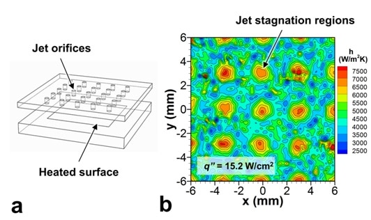
Infrared imagery of thin-foil heat sources is one method to obtain information about the local heat transfer interactions for the design of surface enhancement structures [2]. The local heat transfer coefficient from an array of 25 jets of HFE-7100 [[5]] impinging on a smooth surface undergoing boiling is shown in Figure 1b. Liquid flowing through orifices in a flat plate, as shown in Figure 1a, form the impinging jets. This experimental heat transfer coefficient map shows the simultaneous occurrence of both single- and two-phase heat transfer on the heated surface. The jet stagnation regions, located directly beneath the impinging jets, remain dominated by the single-phase convection provided by the liquid impingement. Boiling occurs primarily between the jets and is evident through the small-scale randomness in the contours of heat transfer coefficient. Boiling surface enhancement structures are most beneficial in these inter-jet areas.
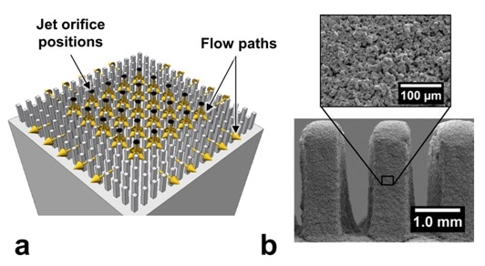
A surface enhancement using pin fins coated with a porous layer is shown in Figure 2 [4,[6]]. This surface both provides ample surface area enhancement (3-fold compared to a flat surface without the pin fins) and promotes enhanced boiling through the application of a porous boiling enhancement coating [[7],[8]], shown in the SEMs in Figure 2b. The fins, 0.5 mm in width, 2.5 mm in height, and spaced 1.5 mm apart, are positioned between the impinging jets to provide boiling enhancement in these regions and to minimally disrupt the impinging liquid flow. The resulting liquid flow paths are largely unobstructed through the heat sink as shown in Figure 2a. The surface shown in Figure 2 has a 25.4 mm square base area to simulate the size of a large-area electronics device.
Enhanced Heat Transfer and Pumping Power Results
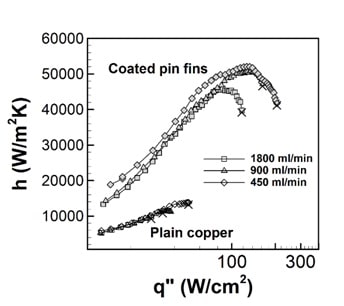
The surface enhancement combined with the impinging jets drastically improves the heat transfer characteristics achievable with this flow geometry, as shown in Figure 3. In this figure, the effective heat transfer coefficient is defined as
(1)
where q [W] is the heat input (after accounting for heat losses), Abase [m2] is the projected area of the base of the heat sink, Tjet [K] is the jet temperature (the jet inlet temperature is subcooled 10 °C below the saturation temperature, 61°C), and Ts [K] is the average base surface temperature.
Compared to a plain copper surface, the coated pin-fin surface drastically increases the heat transfer coefficients and also extends the operating range by delaying critical heat flux (CHF). The enhancement with the impinging jets achieves an effective heat transfer coefficient of h = 52,100 W/m2K at a heat flux of q” = 126.9 W/cm2 at a flow rate of 1800 ml/min. The plain copper surface only reaches h = 13,800 W/m2K at a much lower heat flux of 50.2 W/cm2 at this flow rate. The increase in CHF because of the surface enhancement is also drastic; a 4-fold increase in CHF is observed at all flow rates—with a maximum heat flux of 205.8 W/cm2 achieved at 1800 ml/min.
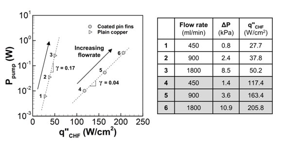
The favorable heat transfer performance presented above only satisfies part of the challenge in cooling electronics devices. The low pumping power characteristics of two-phase jet impingement are what set it apart from other two-phase cooling technologies. Plotted in Figure 4 is the pumping power (Ppump) for each flow rate measured at CHF. This value represents the highest pumping power measured for each flow rate, as lower heat input resulted in less vapor generation and a lower pressure drop at a given flow rate. Plotted on a semi-log axis, the pumping power is shown to increase linearly with the CHF limit. An exponential fit to the data of the form
(2)
reveals that the fitting constant, γ, for the coated pin-fin surface (γ = 0.04) is an order of magnitude lower than that of the plain copper surface (γ = 0.17). The lower constant indicates that the jet array with the coated pin-fin surface can dissipate much larger heat fluxes with only small penalties in pumping power compared to what is needed when using the smooth surface. For example, the pumping power necessary to reach q”CHF = 100 W/cm2 with the plain copper surface would be multiple orders of magnitude higher than that necessary with the coated pin fin surface at the same heat flux, given the trends presented in Figure 4. The pressure drop component of the pumping power for each point is also listed in Figure 4. A maximum pressure drop of 10.9 kPa is observed, illustrating that only a small pressure head is necessary with this two-phase heat sink.
Conclusions and Future Work
Knowledge of the local interactions between impinging liquid jets and boiling can greatly aid in the design of surface enhancement structures. Obtaining this knowledge through local heat transfer measurements is an effective tool for electronics thermal management. The present results show that the coated pin fins complement the flow from the impinging jet array, resulting in low-pumping-power characteristics and greatly enhanced cooling capabilities with dielectric liquids. Further analysis combining local heat transfer measurements with CFD studies [[9]] might provide additional avenues for the design of complementary surface enhancements for non-traditional jet shapes. This design strategy might yield ultimate control over the heat flux dissipation and local heat transfer distributions achievable at a set pumping power with two-phase jet impingement cooling.
References
Figure 1. (a) A schematic diagram of the 5 × 5 array of jet orifices positioned over a smooth flat surface, and (b) the local heat transfer distribution during boiling and liquid impingement from the jet array. The central jet in the array impinges at x = 0 and y = 0 mm.
Figure 2. The complementary surface enhancement shown as: (a) a 3D drawing with the liquid impingement and outflow paths, and (b) SEM images of the porous coating and pin fins after coating.
Figure 3. Effective heat transfer coefficients as a function of heat flux for the coated pin-fin surface and plain copper surface at three volumetric flow rates. CHF for each case is denoted by the symbol ×.
Figure 4. (LEFT) Pumping power at CHF and (RIGHT) the pressure drop measured at CHF for each flow rate.
[1] Ma, C.F., Bergles, A.E., 1983. Boiling jet impingement cooling of simulated microelectronic chips, Heat Transfer Electron. Equip. HTD-28, 5-12.
[2] Rau, M.J., Garimella, S.V., 2013. Local two-phase heat transfer from arrays of confined and submerged impinging jets, Int. J. Heat Mass Transf. 67, 487-498.
[3] Webb, R.L., 1981. The evolution of enhanced surface geometries for nucleate boiling, Heat Transfer Eng. 2(3-4), 46-69.
[4] Rau, M.J., Garimella, S.V., 2014. Confined jet impingement with boiling on a variety of enhanced surfaces, J. Heat Transfer 136, 101503.
[5] 3M, 2009. 3M Thermal Management Fluids, 3M, St. Paul, MN, 1-8.
[6] Rau, M.J., Garimella, S.V., Dede, E.M., Joshi, S.N., 2015, Boiling heat transfer from an array of round jets with hybrid surface enhancements, J. Heat Transfer 137, 071501.
[7] 3M, 2009, 3M microporous metallic boiling enhancement coating (BEC) L-20227, 3M, St. Paul, MN, 1-2.
[8] Joshi, S.N., Dede, E.M., 2015, Effect of sub-cooling on performance of a multi-jet two phase cooler with multi-scale porous surfaces, Int. J. Therm. Sci. 87, 110-120.
[9] Rau, M.J., Dede, E.M., Garimella, 2014, S.V., Local single- and two-phase heat transfer from an impinging cross-shaped jet, Int. J. Heat Mass Transf. 79, 432-436.


