William Maltz, Darryl Moore, and Arun Raghupathy
1. Introduction
With peak loads often in the order of minutes and ergonomic considerations limiting surface temperatures and acoustical noise, handheld devices, such as smart phones or tablets, are excellent candidates for use of phase change materials (PCMs).
Processor loads in handheld products are highly variable. There are many situations where temporary power in system on a chip (SoC) packages can increase due to multiple functionality; for example, social media activity while listening to music, or a short phone call while playing games.
Additionally, handheld consumer products are subject to many ergonomic constraints as a result of their proximity to and direct contact with the user. Surface temperatures must be kept within a comfortable and safe range. If fans are used acoustic noise must be kept below acceptable limits. There are many additional physical constraints on size and weight that restrict the product’s ability to dissipate heat and restrict cooling options. Few existing electronic products are designed specifically for transient thermal loads. In order to manage high temperatures and thermal loads, most rely on throttling and/or added mass to increase thermal capacitance of the materials used in construction.
The design of handheld products with PCMs can extend product working operating range, minimize throttling, and reduce reliance on fans for transient load use cases to reduce acoustic noise and extend battery life. For these reasons, consumer devices are excellent candidates for the introduction of phase change materials. This study looks at opportunities and challenges for applying PCMs to handheld and computing devices using a forced convection tablet as an example.
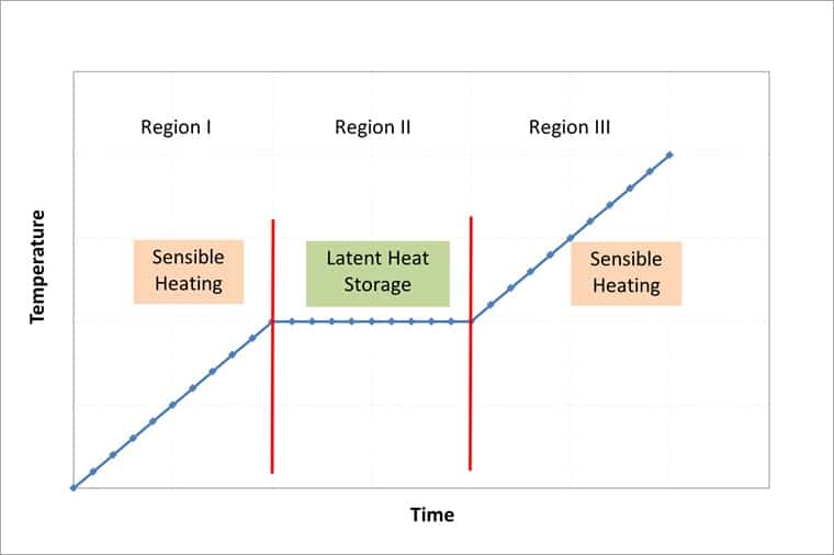
A typical temperature-time heating profile of a PCM under a thermal load, (Figure 1) exhibits linear sensible heating initially, and then undergoes phase transition at a particular melt temperature. During the phase transition heat energy is absorbed by the material while it maintains a constant temperature. Once the phase change is complete, the material continues sensible heating.
Figure 1: Typical PCM heating curve
PCMs have been extensively studied [1,2] and have long been used by industry. The HVAC (heating, ventilating, and air-conditioning) industry, for example, has used PCMs for thermal energy storage. PCM materials have flexibility with respect to their composition and melt temperatures and can be customized to target specific operating temperatures. They have minimal reliability concerns and can be repeatedly cycled without degrading.
Paraffin based PCMs are well suited to electronics applications because they have a high heat of fusion and transition temperatures typically in the range of 5-70C. The material used for this study was a commercially-available composite of paraffin gel material infused into a graphite foam matrix, whose properties are presented in Table 1 [3]. These properties are “effective” ones, in that they represent the combined effect of the graphite matrix and the paraffin gel.” The graphite matrix provides stability for the material and improves its thermal conductivity. The phase change temperature can also be formulated to a range of temperatures.
Table 1: PCM thermophysical properties of PCM material used in study [3]
2. Material performance and model verification.
A simple exploratory experiment was performed with the PCM before applying it to a more complex forced convection tablet environment in order to characterize its behavior and to validate the computational method to be used for the study. The experimental apparatus included a heatsink, a 10 W heat source, 9.5 g of PCM material, and thermocouples placed at various points on both sides of the PCM.
For this study a commercial computational fluid dynamics (CFD) software [4] was used to predict the thermal response of the PCM and test assembly under analysis. The software does not currently allow for the direct simulation of the change in phase of the PCM, so for this analysis the heat of fusion was added to the specific heat versus temperature parameter for the PCM material within the software. This results in an ‘equivalent specific heat’ that incorporates the latent heat storage of the material as a discrete peak in the temperature varying specific heat parameter.
In this case the heat of fusion for the PCM material was distributed over a 3°C temperature range from 42 to 45°C.
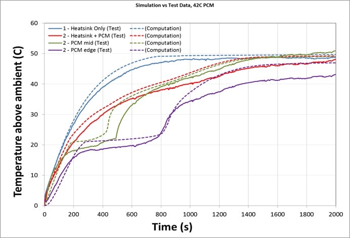
The computational and experimental results are compared in Figure 2, and for the heatsink base temperature are seen to agree within 5°C. The only adjustment required to the computational model to achieve a match to the experimental results was to introduce a contact resistance of 0.02°C m2/W between the heatsink and PCM. This identified surface contact resistance as an important concern in the implementation of PCMs of this type within handheld devices which must be addressed in the design process.
Sensitivity studies were also run where the time step and mesh density were varied and found to show no significant variation in the resulting transient curves, demonstrating that the solution was computationally grid independent.
Figure 2: Experimental (solid) versus computational (dashed) results
for the test assembly (inset)
The results in Figure 2 show that the time period for the system to reach a temperature of approximately 40°C with the addition of the PCM is almost twice that of the system without the PCM. This delay, in the order of 400 seconds or 7 minutes, may be useful in systems with transient loads that occur within that time period.
3. Simulated application of PCM in a forced convection tablet
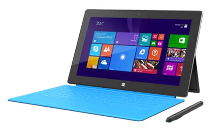
For the main portion of this study the application of PCM material to a popular forced convection tablet, shown in Figure 3, was considered. Previous analyses of this tablet [5, 6] generated a detailed and well calibrated computational model which is used for this study.
Figure 3: Tablet on which the computational model is based for this study
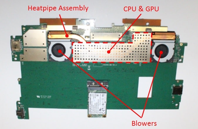
The central processing unit (CPU) and graphics processing unit GPU are the main heat generating components in the tablet. They are mounted adjacent to each other and thermally coupled to a copper heat spreader and dual heat pipe assembly. The condenser ends of the heat pipe are cooled by two small blowers. The heat pipe and blower assembly can be seen toward the top of the image in Figure 4, with the CPU and GPU sitting below the shield approximately mid-way between the blowers.
Figure 4: Tablet cooling system with shield (PCM) area highlighted
(red dashed line)
While there is little space available within the tablet for the addition of PCM materials, the shield that sits over the CPU and heat pipe region encloses a volume of approximately 15 cm3, which is ideally situated for the application of the PCM in the vicinity of the main heat sources.
Attempts to evaluate the PCM experimentally within the tablet were unsuccessful due to the difficulty in maintaining pressure contact between the PCM and heat pipe. The following results are based on the simulated inclusion of approximately 11.8 g of the PCM material placed over the CPU and beneath the shield. The transient heating response of the CPU heat spreader is examined for a 10 W power step. Using the PCM material properties from Table 1 as a baseline, various PCM parameters were varied in order to examine their effects on the transient heating within the tablet environment.
4. Phase Change Temperature
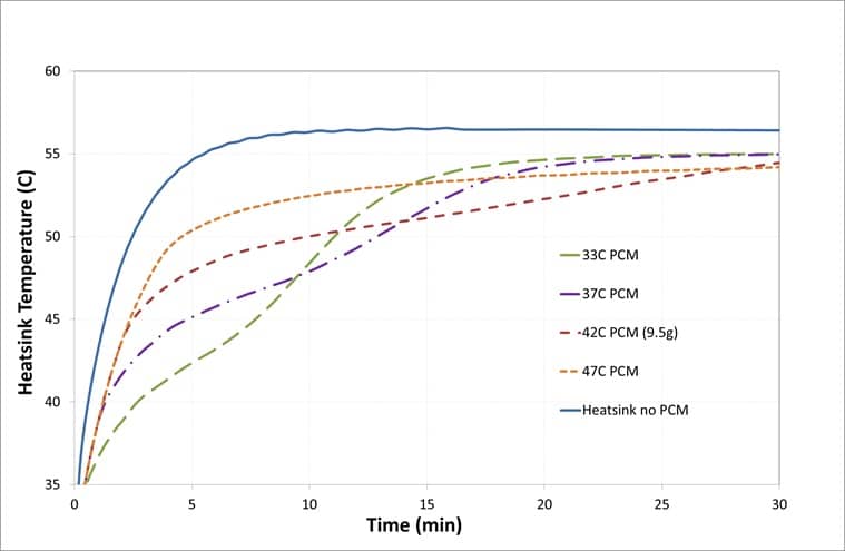
Phase change temperature is a primary consideration in the selection of PCMs. Figure 5 shows the predicted transient system response curves for PCM with phase transition temperatures ranging from 32 to 47°C.
Figure 5: Predicted transient response to varying PCM transition temperature with 11.8g of PCM material (except where noted) in simulated tablet environment
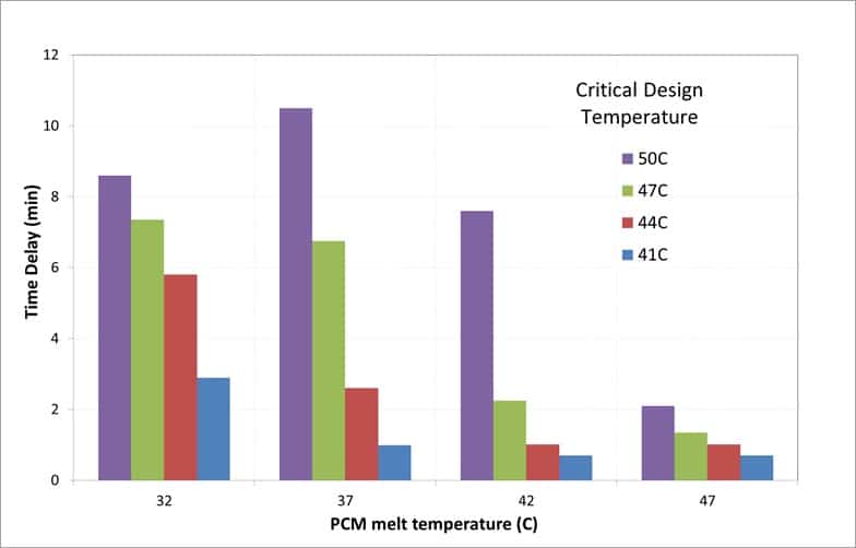
The value of most interest in implementing a PCM solution is the time delay, or increase in the time required for a given temperature to be reached. Figure 6 displays the time delay achieved at four values of critical design temperature (32, 37, 42, and 47°C) for a given PCM melt temperature. For example, at critical design temperature of 50°C, a time delay in excess of 10 minutes is only achieved with a 37°C melt temperature PCM. In order to select the appropriate PCM properties, a good understanding of the system performance and application environments/conditions is required to determine the appropriate critical design temperature for the system.
Figure 6: Predicted transient heating time delay at stated values of critical design temperature, resulting from varying PCM transition temperature
5. PCM Thermal Conductivity
Most PCMs that have transition temperatures and properties suitable for use in electronics thermal management have very poor thermal conductivities. That is the case for paraffin-based PCMs, for which thermal conductivity is normally in the range of 0.1-0.3 W/m-K [7,8]. Due to their low conductivity, heat spreads slowly through the material and the absorption of energy through phase change occurs gradually.
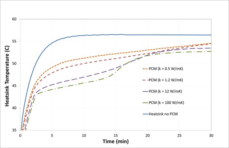
Simulation results in Figure 7 illustrate how improved conductivity can significantly increase the heating time delay experienced by the system and cause the phase transition step to be much more defined. The higher conductivities modeled in these scenarios cannot be achieved with existing materials. Instead, the low conductivity of the materials must be compensated for in the design by the addition of elements such as graphite or metal spreaders to distribute the heat over the PCM.
Figure 7: Predicted transient response to varying PCM thermal conductivity
Figure 8 further illustrates the effects of spreading on the PCM over the heatpipe and blower assembly. The high temperature gradients in the 1.2 W/m-K PCM material make the outline of the heatpipe assembly clearly visible and the addition of spreaders is recommended in order to better distribute heat through the PCM in this case.
Figure 8: Comparison of spreading through PCM in heatpipe / blower assembly, with increased conductivity.
6. Heat Capacity / Volume of PCM
The specific and latent heat capacity of the materials is another important parameter, as it dictates how much heat can be stored and therefore the time delay that can be achieved in system heating. To achieve a required time delay, a high heat of fusion is desired to minimize material volume.
While the volume of PCM required to achieve a given time delay can initially be estimated based on balancing mass and heat of fusion against power dissipation and time, the results in Figures 7 and 9 show that factors such as conductivity and transition temperature will also have a significant effect on the time delay and the volume required must be assessed by accounting for all of these details and the specific environment.
7. Conclusions
For consumer devices, such as phones and tablets, there are many potential advantages to the use of PCMs. In operating conditions involving short term peak loads, they can be used to limit component and hot spot temperatures and can reduce the need for reliance on measures such as fans running at full speed, or throttling of component power. The results of this study indicate that a time delay of 7 to 10 minutes might be achieved for a power dissipation of 10 W if appropriately integrated into the tablet environment. This may be enough to absorb short term peaks in power without the need for throttling or fan speed increases.
There are, however, some disadvantages and difficulties to the implementation of PCMs in hand held devices. The PCM adds weight and complexity to the design, and due to the low thermal conductivity of most PCMs additional spreaders may be required. Contact resistances can be high and the materials must be retained effectively while still allowing for expansion and contraction during changes of phase.
The use of PCMs requires careful design to compensate for these shortcomings and to optimize their performance; never-the-less for suitable applications they can provide a useful means for transient thermal management in handheld devices.
Acknowledgments
The authors would like to thank the following for their assistance:
• Outlast Technologies for providing the PCM samples used for the study.
• Mentor Graphics for providing a Flotherm XT advanced license with transient analysis capabilities.
References
1. Kandasamy, R., Wang, X.-Q., Mujumdar, A.S., “Transient cooling of electronics using phase change material (PCM)-based heat sinks”, Applied Thermal Engineering No. 28, pp 1047-1057, 2008.
2. Wirtz, R.A., Zheng, N., Chandra, D., “Thermal Management using “Dry” Phase Change Materials”, IEEE Semiconductor Thermal Measurement and Management Symposium. 1999, pp 74-82.
3. Outlast Technologies LLC, “Outlast LHS Gel Typical Properties” LHS 90G , Datasheet, Issue 1, Oct, 2014.
4. Flotherm XT, v2.2. Mentor Graphics Corporation, Wilsonville, Oregon, 2015.
5. Nagendran, B., Raghupathy A., and Maltz, W., “Thermal Management of Forced Convection Tablets”, IMAPS Advanced Technology Workshop (ATW), Los Gatos, CA, 2014.
6. Nagendran, B., Raghupathy A., and Maltz, W., “Thermal Management Challenges in Convection Tablets”, IEEE Semiconductor Thermal Measurement & Management Symp., 2015, pp 37-40.
7. Kandasamy, R., Wang, X.-Q., Mujumdar, A.S., “Transient cooling of electronics using phase change material (PCM)-based heat sinks”, Applied Thermal Engineering No. 28, pp 1047-1057, 2008.
Moore, D., Raghupathy A., and Maltz, W., “Application of Phase Change Materials in Handheld Computing Devices”, IEEE Semiconductor Thermal Measurement & Management Symp., 2016, pp 213-217.
8. Wilson, J., “Phase Change Material Thermal Properties”, ElectronicsCooling, May, 2005
