by MP Divakar, PhD, Stack Design Automation
Technical Editor, Electronics Cooling Online
Most electronics cooling problems are not just limited to the computation of temperatures at various points and the design remedies thereof. They also extend to managing the collateral effects of temperature fluctuations. One such effect is the mobilization of thermomechanical stresses in electronic assemblies due to different coefficients of thermal expansion (CTE, commonly denoted ‘a’) of the constituent components. All of the material sets used in manufacturing electronic components today have finite / non-zero coefficients of thermal expansion, and these must be carefully considered in the physical design of assemblies. For the purposes of this discussion, an assembly refers to any product with two or more components joined together using any process prevalent in the electronics industry; a chip package, circuit board with components, etc.
Duty cycles of power dissipating components lead to volumetric expansion and contraction, both with respect to a reference temperature which is most often the ambient / room temperature where the volumetric expansion is close to zero or negligible. Note that the reference temperature does not imply a stress-free state –there may be residual stresses from manufacturing processes, some of which may undergo stress relief or relaxation over time. Good examples of commonly observed stress relaxation are in solder joints of electronic assemblies.
The properties of many materials (especially those used in the electronic assemblies) are seldom isotropic. The assumption of isotopic properties makes sense when one is working with homogeneous materials at macroscopic scales where the effects of microscopic defects and inclusions do not significantly influence the material’s elastic constants such as the Young’s modulus, Poisson’s ratio, CTE, etc. In the absence of isotropy, often practitioners use simplified definitions to deal with anisotropy: transversely isotropic (Wiki) and orthotropic (Wiki). Printed circuit boards (PCB) for example are often categorized as orthotropic materials with nearly equal coefficients of thermal expansion (CTE) in the X-Y plane whereas the Z-axis CTE is often 2X to 10X higher. Further complicating matters, the CTEs change significantly post-Tg, the glass transition temperature (Wiki); the CTEs balloon by 2X or more in any given direction in the post-Tg regime.
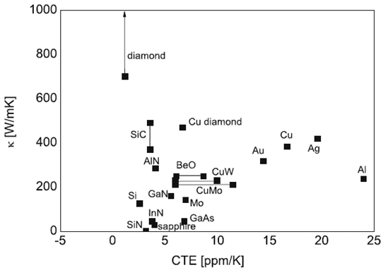
Ideally, electronic packaging engineers look for thermal management materials that have high thermal conductivity and low CTE, high purity, good adhesion and low moisture absorption. Common low CTE materials like Copper Tungsten (CuW), Aluminum-Silicon-Carbide (AlSiC), Kovar, etc., which are commonly used in RF packaging do not offer cost advantages in high volume consumer electronics.

Therefore the drivers to engineer materials whose thermal and mechanical properties can be ‘managed’ come from multiple criteria: cost, performance, quality, reliability, manufacturability, etc. Here is where negative CTE or negative thermal expansion (NTE) materials have been receiving particular attention in the electronics industry lately. One of the materials engineering approaches to minimizing thermomechanical stresses is to engineer the composite materials’ properties including CTEs to a desired range. For example, by combining materials with negative CTE into other materials, thermal expansion can be tailored to specific needs. Using rigorous multiphysics simulation, a layered composite comprising of positive and negative CTE materials can be designed to achieve the target composite CTE.
The electronics industry has a long history with controlled CTE materials. One of the early examples is Invar, the so called “low drift” alloy of Fe and Ni with a CTE of nearly 1 ppm/degK. Invar was and still is one of the most commonly used RF waveguide materials. Invar next made its entry into the world of circuit boards with Cu-Invar-Cu (CIC) offered today by many suppliers in many versions of core and pre-preg stack up.
Negative CTE does not necessarily mean negative or even positive Poisson’s ratio. Confused? Well, you should be! Some elaboration is in order. The lateral deformation as a result of stretching or compressing in the longitudinal really depends on the type of (composite) structure. Here is where the engineering aspect of controlled-CTE materials comes in to play. A rigorous presentation of isotropic negative CTE metamaterials can be found in this reference.
Cellular structures of which Honeycombs are well known can be designed to keep the net expansion zero or positive or even negative. It is even possible to make dense solid microstructures with unbounded thermal expansion. Prof. Roderic Lakes’ (University of Wisconsin, Madison) research group lists a number of publications with cellular composite structures for which CTE can be engineered and is not restricted or bounded by the thermal expansion of the individual constituents.
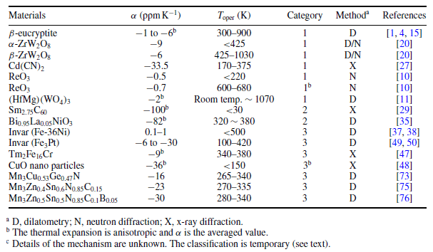
The following table lists some of the low- and negative-CTE materials (source). Zirconium tungstate ZrW2O8 is the most well known in the materials science community as the “geometrically frustrated” metal oxide with large isotropic negative CTE in all directions.
Table 1. Examples of Low- and Negative-CTE Materials (source)
Application in Optoelectronic Packaging
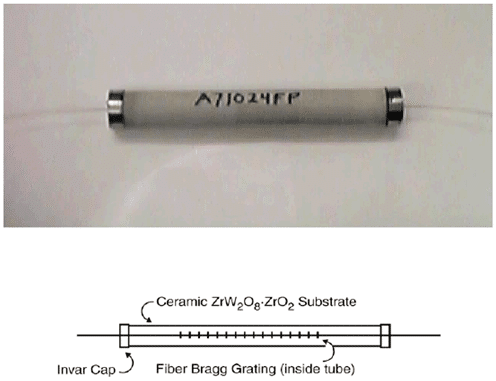
Synthesized and sintered ZrW2O8 along with ZrO2 ceramic has been used in Fiber Bragg Reflectors (FBG) successfully with an overall isotropic CTE of -9.0ppm/degK, resulting in the package performance with +/-0.025nm over ambient temperatures (-40 to 80degC), described in this presentation. This work has the potential to eliminate the need for thermoelectric modules in photonic packages to control wave length shifts with temperature. Passively temperature-compensated optoelectronic “athermal” packages have the potential to lower the cost of packaging and assembly.
Figure 2. Tubular FBG Package (Source)
Application in Circuit Boards
NASA was one of the early pioneers of controlling CTEs of glass fibers and woven fabrics in space and aerospace applications. The NASA publication “Thermal Expansion properties of composite materials” lists some of the important factors that affect laminate CTE as follows:
- fiber and void volumes
- layup angle
- fabric skewness
- stacking sequence
- thermal cycling
- temperature dependence of material properties
- moisture effects
- material viscoelasticity
Unfortunately when it comes to applying the knowledge learned from NASA experiments into the circuit boards, one has to contend with the orthotropic component of the Z-axis. Under the most ideal conditions of symmetric Cu coverage in all layers, the interfacial behavior between metal layers and the dielectric still results in Z-axis CTE values that will be different from those of the X-Y plane.
Nonetheless, progress has been made in designing circuit boards with closely matched CTE of the stack up, albeit in the X-Y plane. Examples like Stablcor, RT/duroid 6035HTC, etc., represent commercially available thermally-engineered circuit board stacks. Electronics Cooling has published earlier the advantages of using CTE-matched thermal core circuit boards. More details can be found here.
Electronics Cooling will continue to update the readers with developments in tailored thermal conductivity and CTE materials. In a follow up, we will discuss how many companies are utilizing thermally engineered materials in electronic packaging in unique ways in a summary of patents on this topic.


