By James Pryde1,2, Weeratunge Malalasekera1, and David Whalley1
1Loughborough University
2Tamlite Lighting
Introduction
The work of Kraus & Bar-Cohen [1] and Bar-Cohen et al. [2] provide a well-defined foundation for the design and optimisation of conventional heatsinks. However, advances in manufacturing processes and increasing access to simulation tools provide new opportunities to develop superior concepts. Comparing different heat sink design concepts, and consequently identifying the most effective design strategies, is a key requirement of development. In this regard, Lasance & Eggnik [3] propose an experimental method that incorporates metrics for ranking heatsink performance for given application. However, numerical methods of capturing a comprehensive, but simple assessment of thermal and hydraulic performance, are also required to support product development and promote the realisation of improved performance. The objective of this article is to establish suitable assessment criteria and apply them to the evaluation of various heatsink concepts for the passive cooling of light emitting diodes (LEDs) used in general lighting applications. This was achieved with the aid of a commercially available computational fluid dynamic (CFD) simulation package.
It is important to relate the criteria on which the heatsink’s performance is judged to the application. The LED is widely recognised as a revolutionary technology in the lighting sector. Its superior lifetime, energy consumption and quality of light is allowing it to rapidly displace established technologies [4]. However, heat (a waste product of their operation) compromises their reliability, efficiency and output characteristics [5]. Effective thermal management is consequently a critical aspect of their implementation. Studies from the US DOE [6,7] highlight the significant environmental benefits of LEDs, promoting their use alongside reliable and low energy consumption thermal management devices. For these reasons passively cooled heatsinks are particularly appropriate and so are the focus of this study.
Definitions of Performance
Performance is an ambiguous term which can relate to; thermal conditions, material content, cost, manufacturability, aesthetics and environmental impact amongst many other parameters. For practical purposes it is necessary to restrict its definition to a few simple, but well defined, criteria.
First and foremost, the heatsink needs to facilitate sufficient transfer of heat to its environment. A common measurement of this property is the absolute thermal resistance, defined by the equation:
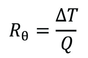
where Rθ is the thermal resistance (K.W-1), ΔT it the temperature difference between the two reference points (K), and Q is the magnitude of thermal power transferred between these two points (W).
Absolute thermal resistance captures the combined effects of all heat transfer modes and associated thermal resistances so provides a useful assessment of thermal management capability. In this study thermal resistance was calculated between the peak heatsink temperature (i.e. base), and the ambient environment (i.e. far field quiescent air temperature).
Thermal resistance relates to specific load conditions. Models such as those developed by Sadeghi et al. [8] offer the necessary tools to compensate for different load conditions but tend to be complex. Standardised thermal load definitions (such as those proposed by Poppe et al. [9]) may be constrained when the application does not adhere to a standard configuration. However, it should be noted that transient thermal testing [10] is an invaluable tool for evaluating and validating thermal resistance characteristics but relies on physical specimen and specialist test equipment. For simulation it is often most practical to assess the thermal resistance characteristics of each case separately.
The same thermal resistance can be established by various heatsink designs, some of which may require less material or exploit superior geometry. Therefore a secondary measure of how effectively the heatsink design develops its thermal resistance is required. A heatsink employing high thermal conductivity material (aluminium in this study), proportionately large surface area and passive cooling is generally described by a small Biot number. Under this condition heat transfer is primarily governed by the body’s interaction with the environment rather than internal conduction. As heat transfer to the environment is facilitated by the heatsink’s surface, achieving the same thermal resistance using less surface area represents better utilisation of the heat transfer interface. A simple measure of effectiveness (E) can therefore be estimated as:
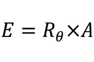
where A is the heatsink wetted surface area (m2). Effectiveness has the units m2.K.W-1, with smaller values representing the combination of lowest thermal resistance achieved with the least surface area.
Heatsink concepts
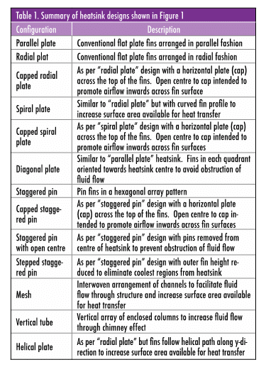
Table 1 summarises a series of heatsink design concepts shown in Figure 1 which are considered in this study. The concepts cover a range of conventional and novel forms. This allows the performance of conventional forms (parallel plate, pin fin) to be benchmarked against verified references while the novel forms provide insight into previously unconsidered (to the author’s knowledge) possibilities. The heatsink bounds were restricted to 60 x 65 x 65 mm (width, breadth and height). The width and breadth were defined by the extents of a commercial LED module (Vossloh-Schwabe WU-M-444/B-NW, Ref. No. 553927). This was chosen so any subsequent experimental analysis could employ a readily available part. Heatsink height was an arbitrary value in keeping with the base dimensions of the part. The heatsink base was a 5 mm thick plate leaving an overall fin height of 60 mm. The wall thickness of the fins was approximately 3 mm, although some small variation resulted from the way these models were defined. The heatsink models were created to allow fin spacing to be modified. Preliminary trials, using CFD analysis, were conducted to identify form which produced the lowest thermal resistance within these bounds.
Simulation definition
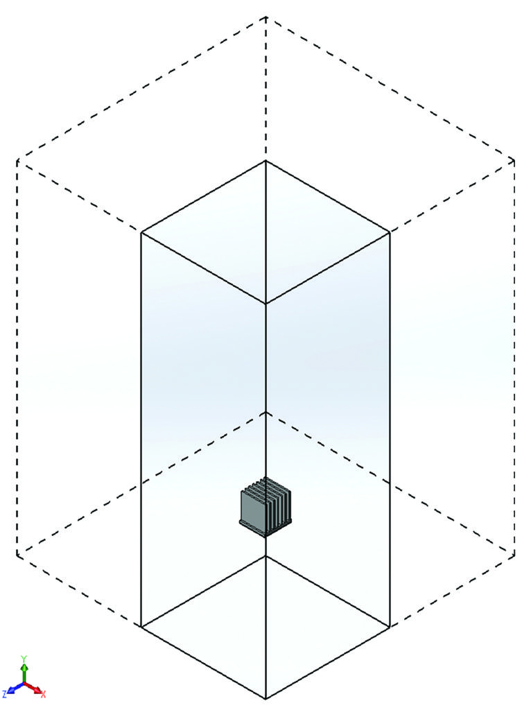
The proposed heatsink models were analysed using a commercially available computer aided engineering software having integrated computer aided design (CAD) [11] and CFD modules [12]. The computational domain used to model the parallel plate heatsink is shown in Figure 2. The computational domain was extended to 0.3 m in x and z direction, -0.07 m to +0.755 m in y direction, with gravity acting in –y direction. Coordinate origin positioned at centre of heatsink base. Symmetry conditions were applied in xy and zy planes when applicable. The computational domain was based on extents of a controlled experimental test chamber used to benchmark boundary conditions. The same setup was used to evaluate each heatsink model.
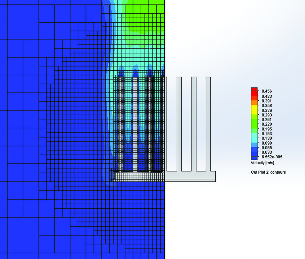
The computational mesh is shown in Figure 3, which is a non-conformal structured Cartesian grid. For a practical compromise between predictive accuracy and processing resources the target computational mesh employed 100,000 to 150,000 cells per quarter domain. At least five cells spanned each inter-fin space. The maximum and minimum heatsink temperatures were used as convergence goals. Convergence criteria were determined automatically by the CFD package.
The heatsink body was treated as a single homogeneous part. It was oriented with the base horizontal (parallel to xz plane). The LED module was included in the simulation model as a separate body attached to the bottom face of the heatsink. The surfaces of this body were exposed to the surrounding environment so permitted heat transfer from the subject. This was consistent across all models. Thermal interface resistance between the two bodies was defined as 0.0001548 K.m2.W-1 in accordance with data supplied for an appropriate interface augmenting material [13]. The LED module comprised four LED packages mounted to an aluminium alloy substrate. As verified in a separate study [14], small features and the internal layers of the substrate (solder mask, copper trace, dielectric) can be omitted from the simulation model but thermal loads should be applied as discrete sources across each component package’s footprint region for maximum confidence in the results Each LED was assigned a thermal power of 1.5 W. Radiative heat transfer was included in the simulation but its role was not optimised. The heatsink surface was assigned an emissivity of 0.1 to represent a reflective silver finish. The low emissivity value represents an approximate “as machined” finish on the basis this would be the simplest to reproduce for future experimental validation. The LED module was assigned an emissivity of 0.8 to approximate the component’s surface finish.
Computational analysis is subject to considerable uncertainty [15]. A preliminary benchmark analysis was conducted on a similar case to validate the simulation parameters employed here. The subject shared the same material properties, surface finish, mechanical configuration, operating parameters, heat source and test environment. The results were within a 5% margin for error. Absolute accuracy was not critical in this study. The objective was to evaluate the performance of different concepts. A relative estimate is sufficient to guide this process, which these simulation conditions achieve.
Results
The resulting thermal resistance and effectiveness of each heatsink model was calculated and plotted in Figure 4.
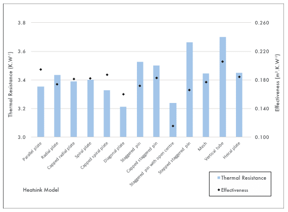
These results were consistent with expectation. The thermal resistance of the models evaluated here ranged between 3.21 K.W-1 (diagonal plate) and 3.70 K.W-1 (vertical tube). With respect to the smallest value this is a margin of 15%. Effectiveness spanned 0.116 m2.K.W-1 (staggered pin with open centre) and 0.206 m2.K.W-1 (vertical tube). This represents a margin of 78% compared to the best performing. Some key points to summarise are:
- There was no apparent correlation between thermal resistance and effectiveness. Neither criteria offered a complete assessment of performance.
- The basic parallel plate heatsink model achieved a thermal resistance of 3.35 K.W-1 but was one of the least effective designs (0.195 m2.K.W-1).
- The radial plate heatsink imposed higher thermal resistance (3.44 K.W-1) but was also more effective (0.174 m2.K.W-1) than the parallel plate heatsink design. This appeared to be because the arrangement of fins did not obstruct airflow from any direction but provided an overall smaller surface area restricts heat transfer.
- The spiral plate fin arrangement provided greater surface area than the radial plate heatsink. This resulted in 0.04 K.W-1 (1.1%) lower thermal resistance but its poor utilisation led to a 0.008 m2.K.W-1 (4.6%) decrease in effectiveness.
- The diagonal plate heatsink offered the lowest thermal resistance. A number of factors appeared to contribute to this. The parallel fin arrangement maintained the optimum spacing for fluid flow, the fin positions optimised thermal conduction away from the source, and the geometry did not obstruct fluid flow from any direction.
- Excluding pins from the centre of the staggered pin heatsink appeared to enhance fluid flow whilst removing ineffective heat transfer surfaces. Consequently it provided one of the lowest thermal resistances (3.24 K.W-1) along with the highest effectiveness (0.116 m2.K.W-1).
- As demonstrated by the staggered pin and stepped staggered pin design, removing the coolest portions of the heatsink showed limited benefit. Between the two models there was just 0.006 m2.K.W-1 (3.5%) improvement in effectiveness but an accompanying 0.13 K.W-1 (3.7%) increase in thermal resistance.
- In all instances, adding a horizontal cap to the top of the heatsink reduced thermal resistance (by an average of 1.5%) but also compromised the effectiveness (4.2%) demonstrating the additional surface area was poorly utilised
- Restricted thermal transfer through the structure and poor fluid flow hinders the performance of the vertical tube and mesh heatsinks. However, these models did reveal the small buoyancy driven, passive convection forces can be used to manipulate entrained fluid flow.
- The vertical tube concept offered the worst performance by under both criteria (thermal resistance and effectiveness) so would be unattractive for further consideration.
- The helical plate heatsink was 0.010 m2.K.W-1 (5.7%) less effective than straight radial fins. This appeared to be because the helical form obstructed fluid flow and due to the way it was defined reduced the fin thickness. As a result fin efficiency and performance was reduced.
Conclusions
The primary objective of this study was to develop criteria to compare the performance of different heatsinks. The results demonstrated simple, but well defined, methods to achieve this. They were applied to various heatsink designs and those offering superior performance were revealed. This ability can be used to direct development towards better performing strategies or quantify the impact of any changes.
A conventional parallel plate fin heatsink was neither the most effective or offered lowest thermal resistance. By employing a superior design it was possibly to reduce thermal resistance by 0.14 K.W-1 (4.2%) or improve effectiveness by 0.079 m2.K.W-1 (40.5%). A pin fin heatsink with no pins at its centre was the most effective (0.116 m2.K.W-1) concept while a heatsink employing parallel plate fins in a diagonal arrangement provided the lowest thermal resistance (3.21 K.W-1). Only thirteen simple heatsink models were analysed in this study. A thorough and definitive comparison of performance would demand more detailed assessment. For more complex models, incorporating multi-objective optimisation, the number of parameters to consider would quickly become impractical. In an effort to manage this a number of constraints were applied. A broader exploration of various concept’s potential without the arbitrary physical constraints imposed here would be valuable. It was the author’s belief that the results still provide an acceptable indication of performance and demonstrate the ability to determine which concepts offer the most potential for development.
Acknowledgements
The Authors wish to acknowledge Tamlite Lighting Ltd. for their unconditional support for, and contribution of various resources to, this investigation.
References
[1] Kraus, A.D., and Bar-Cohen, A., Design and Analysis of Heat Sinks, First Edition, John Wiley and Sons, New York, USA (1995).
[2] Bar-Cohen, A., Bahdur, R., and Iyengar, M., “Least-Energy Optimisation of Air Cooled Heat Sinks for Sustainability-Theory, Geometry and Material Selection,” Energy, Vol. 31, No. 5, pp. 579-619 (2006).
[3] Lassance, C. J. M., and Eggnik, H. J., “A Method to Rank Heat Sinks in Practice: the Heat Sink Performance Tester,” In proceedings of the 21st Annual IEEE Semiconductor Thermal Measurement and Management Symposium (Semi-therm), San Jose, CA, USA, March 15–17, 2005, pp. 141-145.
[4] McKinsey & Company, “Lighting the way: Perspectives on the Global Lighting Market,” Second Edition (2012), https://www.mckinsey.de/files/Lighting_the_way_Perspectives_on_global_lighting_market_2012.pdf, accessed August 15, 2016.
[5] Chang, M. H., Das, D., Varde, P. V., and Pecht, M., “Light Emitting Diodes Reliability Review,” Microelectronics Reliability, Vol. 52, No. 5, pp. 762-782 (2012).
[6] US DOE, “Life-Cycle Assessment of Energy and Environmental Impacts of LED Lighting Products. Part 1: Review of the Life-Cycle Energy Consumption of Incandescent, Compact Fluorescent, and LED lamps” (2012), http://energy.gov/sites/prod/files/2015/10/f27/2012_LED_Lifecycle_Report.pdf, accessed August 14, 2016
[7] US DOE, “Life-Cycle Assessment of Energy and Environmental Impacts of LED Lighting Products. Part 2: LED Manufacturing and Performance” (2012), http://energy.gov/sites/prod/files/2015/10/f27/2012_led_lca-pt2_0.pdf, accessed August 14, 2016.
[8] Sadeghi, E., Bahrami, M., and Djilali, N. “Thermal Spreading Resistance of Arbitrary-Shape Heat Sources on a Half-Space: A Unified Approach,” IEEE Transactions on Components and Packaging Technologies, Vol. 33, No. 2, pp. 267-277 (2010).
[9] Poppe, A., Kolla, E., Toth, Z., and Simonovics, J., “Characterization of Heat-Sinks of Socketable LED Modules using Thermal Transient Testing,” in Proceedings of the 20th International Workshop on Thermal Investigations of ICs and Systems (THERMINIC), Greenwich, London, UK, September 24-26, 2014.
[10] Farkas, G., and Poppe, A., “Thermal Testing of LEDs,” Chapter 10 in: Thermal Management of LED Applications: Volume 2 – Solid State Lighting Technology and Application, Lasance C.J.M. and Poppe A. (Eds), Springer, New York, USA, pp. 73-165 (2014).
[11] Dassault Systemes, Solidworks Professional 2015 x64 Edition, SP 2.1, http://www.solidworks.com/sw/products/3d-cad/solidworks-professional.htm, accessed 15th August 2016.
[12] Dassault Systemes, Solidworks’ Flow Simulation 2015 SP2.0. Build: 2990, http://www.solidworks.com/sw/products/simulation/flow-simulation.htm, accessed August 15, 2015.
[13] HALA CONTEC Graphite Foil TFO-S-CB, available at: http://www.hala-tec.de/fileadmin/user_upload/datenblaetter-en/E_HALA_TFO-S-CB.pdf, accessed August 15, 2016.
[14] Pryde, J., Whalley, D., and Malalasekera, W., “An Assessment of Computational Fluid Dynamic Simulations and Appropriate Simplifications used for the Development of LED Luminaires,” in Proceedings of the 20th International Workshop on Thermal Investigations of ICs and Systems (THERMINIC), Greenwich, London, UK, September 24-26, 2014.
[15] Lasance, C.J.M., “The Conceivable Accuracy of Experimental and Numerical Thermal Analysis of Electronic Systems,” IEEE Transactions on Components and Packaging Technologies, Vol. 25, No. 3, pp. 366-382 (2002).

Born in 1988 in Stafford, UK. He acquired an MSc degree in mechanical engineering at Staffordshire University in 2011. He has since been working in industry and is currently based at Tamlite Lighting (UK) as Senior Luminaire design engineer. In 2016 he became a chartered engineer with the Institute of Mechanical Engineers. Alongside working in industry he is pursuing a doctoral degree with Loughborough University where he is exploring appropriate thermal management techniques for LED luminaires within a commercial context.
Contact Information
James Pryde
Loughborough University
Loughborough, LE11 3TU, UK
Email: j.r.pryde@lboro.ac.uk

Born in Blackburn, Lancashire and attended Ledbury Grammar School, Herefordshire. Graduated from Loughborough University in 1984 and subsequently worked as a research engineer both at Loughborough University and at the Lucas Advanced Engineering Centre in Solihull, Birmingham. Appointed as a lecturer in 1990 and promoted to Senior Lecturer in 1998. Visiting Professor, Chalmers University of Technology, Göteborg, Sweden and Nanyang Technological University, Singapore 2001/2002.

Born in Sri Lanka, attended St. Thomas’ College, Mount Lavinia, Colombo. University Education at University of Peradeniya, Sri Lanka, Graduated 1983. Obtained Ph.D. and D.I.C. from Imperial College of Science Technology and Medicine, University of London, 1988. 1984 – 85: Assistant Lecturer, Dept. of Mechanical Engineering, University of Peradeniya, Sri Lanka. 1985 – 89: Research Assistant/Postdoctoral RA (1989) at the Dept. of Mechanical Engineering, Imperial College, London. Joined Loughborough University as a lecturer in 1989.


