by MP Divakar, PhD, Stack Design Automation
Technical Editor, Electronics Cooling
With many nations joining the race of sending satellites out to space, the number of orbiting space debris is increasing year after year. This NASA portal estimates the number of space junk as over 500,000 orbiting earth at speeds of 17,500mph or higher. Most of the half-million plus objects are estimated to be between 1 and 10 cm in diameter. Of the remaining debris currently in orbit, more than 18,000 objects are estimated to be larger than 10cm. The number of particles smaller than 1.0cm probably exceeds tens of millions! (Note that smaller space debris includes dust from solid rocket motors, degraded surface flakes and even coolant released by Russia’s Radar Ocean Reconnaissance Satellite (RORSAT) nuclear powered satellites.)
Larger space debris poses serious threat to orbiting space craft and can render them useless upon impact. Space debris as small as 1cm or less can also cause serious damage to the space craft by impacting the solar panels. They can also cause the breach of controlled environment and pressure in space suits of space-walking astronauts. Owing to their higher orbital, the geosynchronous (GEO) satellites are usually struck by very small debris and micrometeoroids whereas low earth orbit (LEO) satellites face more hazards from orbiting space debris of all sizes.
Many governmental bodies have deployed resources to track the orbiting space debris using ground-based telescopes as well as orbiting telescopes (for example, LDEF). Space debris larger than 10 cm) are tracked routinely by the U.S. Air Force Space Surveillance Network (SSN), the Russian Space Surveillance System (SSS), and the French Grande Réseau Adapté à la Veille Spatial (GRAVES). Ground-based radars can track objects as small as 3mm but the existing ground-based telescopes (foregoing examples) lack the capabilities to detect smaller and less luminous objects.
The Defense Advanced Research Projects Agency (DARPA) of United States initiated a program in 2002 for ground-based surveillance of space-based debris. DARPA’s SST program addresses some of the serious shortcomings of all ground-based telescope / radar surveillance systems by enabling capabilities to monitor small and faint objects in GEO orbits. As documented on the DARPA website, the space surveillance telescope achieved first light in February 2011, after nearly a decade of development and trials. Currently located in the White Sands Missile Range in New Mexico, the SST is being moved to the Harold E. Holt Naval Communication Station in Western Australia.
In this article, Electronics Cooling is pleased to bring you more information on the current state of the project and further information on the thermal management of the electronics modules in the SST. Developed at MIT Lincoln Lab, the SST features the first implementation of recent advances in curved focal plane technology enabling a wide field of view, rapidly scan-able, and three-mirror, 3.5-meter telescope with 3.5deg field of view. These YouTube videos (link1, link2) provide more information on how the SST operates.
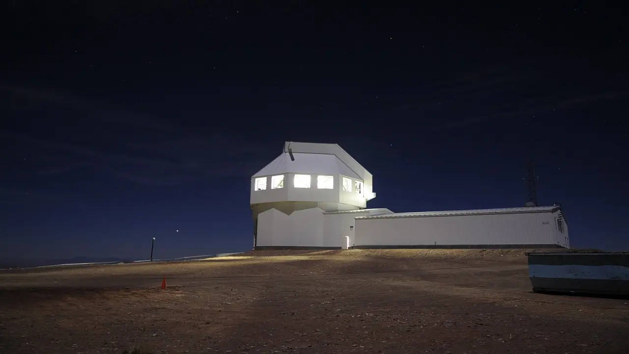
The following figures show a CAD model and several views of the built SST system. Though slated to be moved to Australia, the SST is currently located at 8000ft elevation in the White Sands Missile Range of New Mexico. Eventually, there will be three to four such locations worldwide to insure complete coverage of near earth asteroids and space debris.
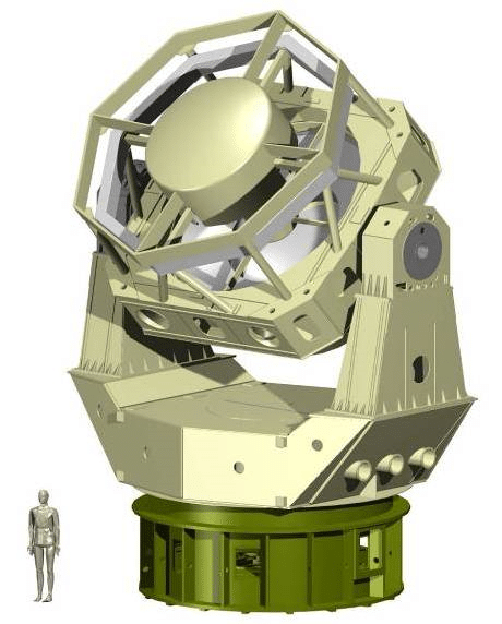
(Ref)
The SST system is a Mersenne-Schmidt (wiki) telescope design with a highly sensitive curved mosaic focal surface CCD (charge-coupled device, wiki) camera. There are 12 CCD devices aligned to the curved focal surface. Each CCD has 2048 by 4086 matrix of 15μm pixels.
It is of critical importance to maintain the temperature gradients across CCD arrays as low as possible. This is due to the fact that thermal energy can excite extraneous electrons into the image pixels making it harder to distinguish the ‘dark current’ photoelectrons from those of the actual image. Thermoelectric (TE) modules are typically employed in cooling of CCD arrays to keep thermal gradients at a minimum; the reader may refer to an earlier Electronics Cooling’s article on the application of TE modules in cooling CCD arrays. Lower temperatures benefit the operation of CCDs but in general, temperatures below 120degC render CCDs non-functional.
Detailed information on the electronic / electro-mechanical packaging of the SST system still remains classified. The figure below shows the wide field of view CCD in MIT’s Lincoln lab.
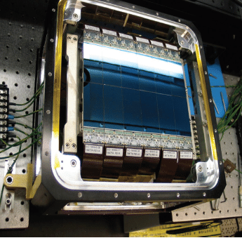
The figure below shows one of the 12 imagers with a curved focal surface with corrections for optical aberrations. There may be TE coolers underneath each CCD but that information is not freely available. To curve the silicon wafers of each CCD and precisely align them, MIT’s Lincoln Lab used new manufacturing and metrology techniques. Three components of the CCD imager –the sensing layer, its associated etched circuitry, and a carrier Silicon wafer were altered to achieve the desired curvature(see figure below).
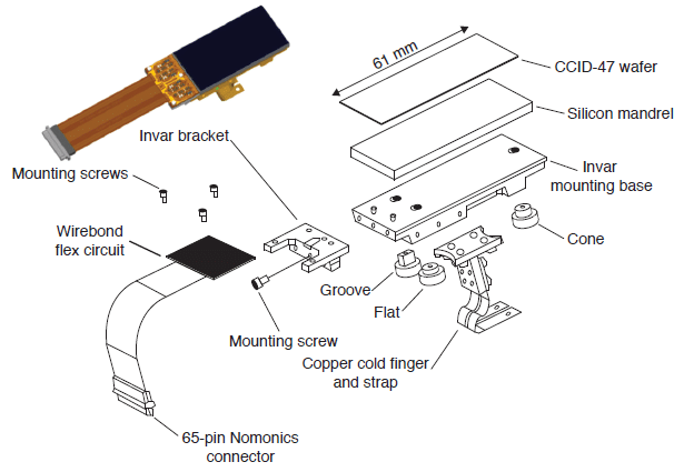
The steel structure of the SST also figures prominently in thermal management –the temperatures fluctuate over a range of -12degC in winter to +25degC in summer. Dome pre-conditioning is used to prevent convection losses from the optics.
There are 58 temperature sensors on the telescope structure and a model generated from the sensor readings helps in minimizing the spherical aberration of mirrors. The temperature model based on the sensor readings provides the best indication to SST system’s thermal equilibrium to keep the telescope in focus as the ambient temperature varies. The model also provides local isothermal boundary temperatures to maintain the curved CCD arrays at temperatures to keep dark currents to a minimum.
As more updates become available, Electronics Cooling will publish updated blogs on this every interesting and technically challenging application of thermal management in large space telescopes. Stay tuned!
