Scott D. Kennedy
Senior Product Manager
Rogers Corp
Power Electronics Design Trends
Power electronics and associated thermal design is an essential early stage of many product development efforts, especially with growing demand for vehicular and industrial applications. Current trends to increase vehicular driver assistance features, reduce the carbon footprint of vehicles, implement vehicle electrification, and incorporate light-emitting-diode (LED) lighting in automotive and industrial applications all contribute to the growing importance of power electronics.
Electric vehicles require effective thermal management solutions in their powertrain control units. These units include DC/DC converters for either engine management or transmission control. Electric vehicles also feature chassis control units for such functions as electronic power steering. These electric vehicle subsystems operate at high power levels and generate heat that must be dissipated effectively, but without adding excessive weight and volume to the vehicle.
Vehicular lighting is also making a technological transition requiring effective thermal management solutions. Compared to their incandescent predecessors, LED headlights provide improved visibility and enhanced driver safety. But this added performance is not without a price: more than 60% of electrical power supplied to an LED headlight is converted to heat. If heat is not removed from the LED junctions, the elevated temperatures can compromise LED performance and reliability.
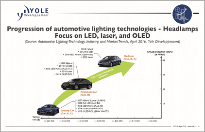
The widespread acceptance of this newer headlight technology is expected to drive the growth of the vehicular LED lighting market in the coming years. For example, 100% of the D, E, F-segment cars (luxury and premium vehicles) and 60% of the B, C-segment cars (medium quality vehicles) are expected to have LED headlamps by 2022. Figure 1 below highlights the trends of the lighting market from 2007 and expected through 2025.
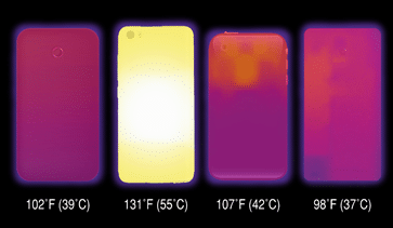
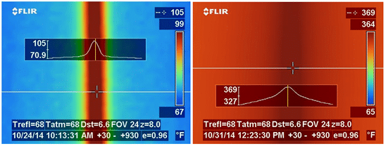
Thermal management is also important for mobile electronics products. The current trend of smaller mobile/handheld electronic devices with increased processing power has resulted in circuits with higher-power-density microprocessors and other semiconductors with thermal management challenges. Figure 2 is a representation of thermal images and external temperatures for a number of different smart phones.
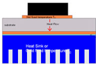
The increased power densities of modern mobile devices has caused circuit designers to reconsider their choices of circuit substrate materials, since those materials must now play a greater role in a mobile device’s thermal management. The upper operating-temperature limit of most circuit substrates is about 100°C above room temperature (+25°C) or at about +125°C. Traditionally, heat sinks have helped dissipate heat in mobile devices. However, with competitive pricing pressures and the trend for miniaturization, a heat sink may no longer represent a practical thermal solution in a mobile electronic device. Cooling by either external convection air cooling or the use of heat pipe technology is an alternative thermal management approach, but both of these techniques require an additional secondary system adding weight and cost to the final design. They also introduce potential hurdles of quality and reliability that may need to be overcome. Figure 3 below represents a traditional post-attached heat sink approach.
Thermally enhanced printed circuit boards (PCBs) like 92ML™ Series and 92ML™ StaCool™ Series materials represent a practical, cost-effective thermal management solution for electronic circuit designs that must minimize weight and volume. Such PCBs can be used in multilayer circuits in place of traditional FR-4 circuit laminates and prepreg materials. The circuit footprint remains small and effective thermal management is achieved without the addition of bulky heat sinks or other heat removal approaches. Figures 4 and 5 describe prepregs and laminates for thermally enhanced PCBs.


Metal-core printed circuit board materials (MCPCBs) or insulated metal substrates (IMS) like 92ML StaCool materials offer cost-effective, space-efficient solutions for thermal management in modern power modules. They eliminate the need for large, pre-machined heat sinks, thermal pads, thermal greases, springs, wave soldering, and the manual labor associated with the assembly of the traditional power modules (Fig. 6).

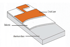
The presence of the heat sink is a necessity in order to remove excessive heat from the module. Figure 7 below highlights the importance of a heat sink in assisting the thermal dissipation.
Design Advantages of Thermally Enhanced PCB Materials
PCB-based thermal management solutions provide many benefits for designers, including design advantages, decreased labor requirements, improved product quality, and lower capital costs.
Compared to traditional ceramic modules, the PCB material approach has the following advantages:
- The use of PCB materials instead of ceramic or other active cooling techniques allows for the use of environmentally friendly materials that are compliant with the end customer and/or local legislative requirements.
- Since dielectric materials are lower in density than ceramic material, the PCB approach reduces vehicle weight for lower CO2
- Use of established PCB technology permits large economies of scale.
- Since ceramic modules are limited in the area of embedded devices, the PCB approach allows for integrated designs which incorporate processors and/or power devices within the PCB itself. This is useful for minimizing circuit board heights in tight spaces.
The integration of the heat sink within the PCB material eliminates the need to attach a heat sink separately in the module production process. This eliminates the need for thermal pads, greases, springs, clamps, heat sink assembly, and wave soldering of components. It also allows for the use of press fit connections rather than manually inserted and wave soldered connectors. This greatly simplifies the assembly process as shown in Figures 8a and 8b below.


As illustrated in detailed process steps in Figure 8a, the IMS approach offers the following advantages over a standard post-attached heat sink:
- Eliminates need for module preassembly.
- Eliminates need for manual insertion of surface-mount components, resulting in lower rework or touch-up of soldered surface-mount components.
- Allows automated solder reflow and assembly, minimizing the overall cost of labor.
- Reduction of labor costs and processing steps offset any added automated assembly costs.
- Reduction of module components, with fewer opportunities for failure.
- Reduction of operator contact for more consistent product quality.
Key Material Parameters
In selecting a thermally enhanced PCB material for a thermal management application, designers should be aware of some critical material parameters related to temperature:
Thermal Conductivity
Thermal conductivity is a direct measure of a material’s ability to conduct heat transfer. It is the most important property of a thermally enhanced PCB dielectric material. Thermal conductivity is a necessary property to maximize when other means of thermal transfer are not available (i.e. copper vias, heat sinks, coins, active cooling, etc).
The thermal heat flow across the thickness of a dielectric material is inversely proportional to thermal resistance as shown in equations 1 and 2 below.
(1)
(2)
Where Q = heat flow (W), = change in temperature (K), = absolute thermal resistance (K/W), L = thickness (m), A = area (m2), and k = thermal conductivity (W/mK).
The absolute resistance of the thermal heat transfer can be viewed in much of the same way as the resistance to current flow in an electrical circuit. Figures 9a and 9b below show the two most common circuit resistance configurations.

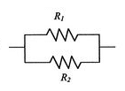
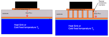
Equations 3 and 4 below highlight the two most common ways to interpret the thermal resistance path across the dielectric material.

(4)
Figure 10 below highlights the practical application of equations 3 and 4 to actual module construction options.
Standard PCB materials have thermal conductivity values of 1.0 W/m-K or less as measured in the z-axis of the material. Typical FR-4 circuit material has thermal conductivity of 0.3 W/m-K. Thermally enhanced PCB materials have thermal conductivity of 1.5 W/m-k or higher in the z-axis. High-quality thermally enhanced PCB material has in-plane thermal conductivity equal to or greater than the z-axis value, so that heat spreads in the x-y plane of the material as well as through its thickness. This is particularly important when copper plated through holes (PTHs) cannot be placed near a source of heat or when heat dissipation from a module’s edges is particularly important. Dielectric material in-plane thermal conductivity of 3.0 W/m-K or higher is considered to be excellent.
Glass Transition Temperature (Tg)
The glass transition temperature, Tg, is a dependable indicator of the thermal stability of a dielectric material. Above Tg polymers have significantly more molecular mobility. This results in a lower modulus and a much greater expansion rate. If the Tg value is too low, the material will be compromised during exposure to high temperatures, such as during assembly. Lead-free solder attachment typically requires exposure to a temperature of +260°C. If a material softens too early during assembly exposures, there is a risk of blistering, delamination, warpage, or other functional issues. Tg values of +150°C or more are typically required to ensure that the material will survive the necessary thermal exposures.
Coefficient of Thermal Expansion (CTE)
The coefficient of thermal expansion (CTE) describes the expansion rate of a material with temperature. In a PCB, the expansion rate of the dielectric material must be matched to the other materials in the circuit structure otherwise stress will occur at the junctions of different materials, causing board warpage and PTH reliability issues. Ideally, a PCB should have an in-plane CTE value that is between the CTE of copper (17 ppm/°C) and the CTE of aluminum (22 ppm/°C). This will ensure MCPCBs or IMS substrates with optimal coplanarity, with low probability of warpage during assembly and normal operation.
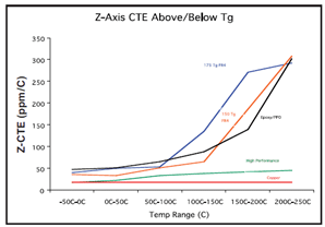
The z-axis or out-of-plane CTE of a PCB material is equally important as the x-y in-plane CTE. Dependable thermoset materials should have z-axis CTE values below Tg that are less than 50-60 ppm/°C. Thermoset materials with z-axis CTE values below Tg that are less than about 30 ppm/°C are considered excellent. Lower z-axis CTE values will result in higher PTH reliability as well as optimal surface component continuity. Figure 11 below shows the impact of Tg on the z-axis CTE.
Maximum Operating Temperature (MOT)
The printed circuit material must have the capability to survive for many years at the expected operating temperature of the modules that they will be in. Underwriters Laboratories (UL) has a testing protocol whereby accelerated aging testing is performed that replicates the exposure that the material would see for a testing time of 100,000 hours (or 11.4 years). This MOT test protocol is used to screen circuits for failures such as warpage, blistering, delamination, etc. Good thermoset circuit materials will have an MOT capability of +125°C or more. Excellent materials will have an MOT capability of +140°C or more. The ultimate MOT rating needed is dictated by the end use requirements of the circuit.
Environmental Requirements
PCB materials for consumer application are typically required to have a UL 94 V-0 flammability rating from Underwriters Laboratory (UL). This rating ensures that a dielectric material will self-extinguish within 10 s after exposure to a direct flame. The requirement is application specific and a UL 94 V-0 rating is not required for many applications, such as in space applications.
Circuit materials are at times required to be free of lead-containing components. This lead-free, Restriction of Hazardous Substances (RoHS) condition, also known as Directive 2002/95/EC, originated with the European Union (EU). It restricts the use of six hazardous materials found in electrical and electronic products. All applicable products in the EU market after July 1, 2006 must pass RoHS compliance. RoHS impacts the entire electronics industry and many electrical products as well (RoHS Guide, 2016). This lead-free requirement mostly impacts the solders used with circuit materials. Removal of lead from solder resulted in a need for higher eutectic melting temperatures. As a general rule, the lead-free solder reflow profile is set to a peak temperature of +260°C. Reflow profiles for solders with lead have peak temperatures as low as +225°C.
Circuit materials may also sometimes be required to be free of halogen-containing components. This is an emerging, typically environmentally driven requirement for electronic circuits and mostly found in products for European markets. Few thermoset circuit materials meet the most stringent combination of UL 94 V-0 flammability, RoHS compliance, and halogen-free composition.
In summary, the growth of power electronics applications is fueling a clear need for reliable, thermally enhanced PCB materials to aid in thermal management. Effective thermally enhanced PCB materials like 92ML StaCool Series materials offer many design, labor, cost, and quality advantages over traditional heat-sink power electronic module design approaches. Selecting a thermally enhanced PCB material for a power electronics design is a matter of meeting the requirements of an application, with optimum PCB performance that includes z-axis thermal conductivity of better than 2.0 W/m-K, x-y in-plane thermal conductivity of 3.0 W/m-K, z-axis CTE of less than 50-60 ppm/°C, x-y in-plane CTE between 17 and 22 ppm/°C, and MOT of better than +140°C. Many applications may also require a UL 94 V-0 flammability rating as well as compatibility with RoHS and halogen-free requirements.
Scott Kennedy is Senior Product Manager for Rogers Corp. He has been with the company for 16 years, nine of which were spent in research and development, six in sales, and the past year in his current position. He holds eight US patents and has authored or co-authored four industry articles. Scott holds a BS in Chemical and Materials Engineering and a MS in Polymer Science, both from the University of Connecticut. He also has six years of US Naval submarine nuclear engineering experience.
References
(2016, August 6). Retrieved from RoHS Guide: http://www.rohsguide.com/
- Aguayo, M. K. (2006, June). High Frequency Materials: Setting the Pace for Lead Free Processing. Circuitree.
John Coonrod. (2015). Thermally, Electrically Conductive Adhesive, Manages to Control Heat in PCB’s. IPC APEX. IPC.
Yole Developpement. (2016).
