Introduction:
It is interesting how different parts of a value chain speak differently, sometimes wildly differently, about a product or feature but they may use the exact same words. For example, both the consumer and the thermal engineer want the device to have “cool” features. Wireless charging is one such hardware feature [1].
Wireless charging was included in over 250 million devices in 2016, expected to grow at a 85% CAGR until 2019. As of today, around 15 automobile models have announced the inclusion of consoles within the vehicle for wirelessly charging devices such as smartphones [2], and Dell has demonstrated the world’s first laptop charging solution [3] at CES 2017 with a projected product release in mid-2017.
Further, while several handset manufacturers already include it in their flagship devices, it is expected that both of the top two smartphone manufacturers of the world will include this feature by the end of 2017. The key technical attributes of the wireless power solution, especially for the antenna, include spatial (xy) freedom, high performance regardless of environment, and being minimally invasive. High performance implies high charge rates without causing heating concerns.
This article pertains to wireless charging of devices using Near Field Magnetic Coupling (NFMC) in the consumer electronics industry; more specifically it refers to devices that operate in the high-coupling (k> 0.5) regime, commonly referred to as the inductive mode.
There are wireless power standards working towards ensuring interoperability between devices [4, 5]. This brief addresses the sources of thermal concerns and some common design practices and material choices to help implement ultra-thin form factors that are also thermally robust, especially on the receiver (device) side. Thermal effects are extremely important because it may lead to consumer inconvenience, device malfunction, and in extreme cases, device damage.
Wireless Power and the Mobile Device
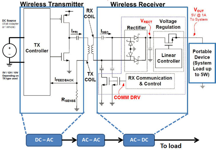
The Wireless Power system can be viewed as a DC-DC converter with an air-core transformer as illustrated in Fig. 1 [6]. The figure illustrates a circuit schematic of an exemplary low frequency (around 100-400 KHz) system using a half-bridge type inverter to drive the transmitter antenna (equivalent to the primary coil of the transformer). The system may utilize antennas that are highly resonant, mildly resonant, or not resonant at all; it depends on the use of capacitors to alter the reactive impedance looking into the antenna. In the consumer electronics realm, the frequency of operation ranges from approximately 100 KHz to about 13.56 MHz.
Thermal Sources in a Wireless Power System
The major sources of heat in this system are the I2R losses (Joule heating) in the antennas, joule heating due to eddy currents in the shielding material and any metallic components that are in the path of magnetic flux lines, switching losses in the power stage, and losses in passives (e.g. rectifiers). Further, it should be noted that the heat is generated by both the transmitter system and the receiver system, and a portion of the heat from the transmitter side will flow to the receiver via a combination of conduction and convection. Here, we will focus on the magnetics (i.e. antennas + shielding) on the receiver side which is one of the primary sources of heat in the device.
Consider the following equations:
Where VRx-ind is the voltage induced in the receiver antenna, ω is the angular frequency, k is the coupling coefficient, LTx is the inductance of the transmitter antenna, LRx is the inductance of the receiver antenna, ITx is the current through the transmitter antenna, IRx is the current through the receiver antenna, RAC (Coil) is the AC resistance of the antenna at the operating frequency, and ZAC load is the effective impedance looking into the receiver circuit.
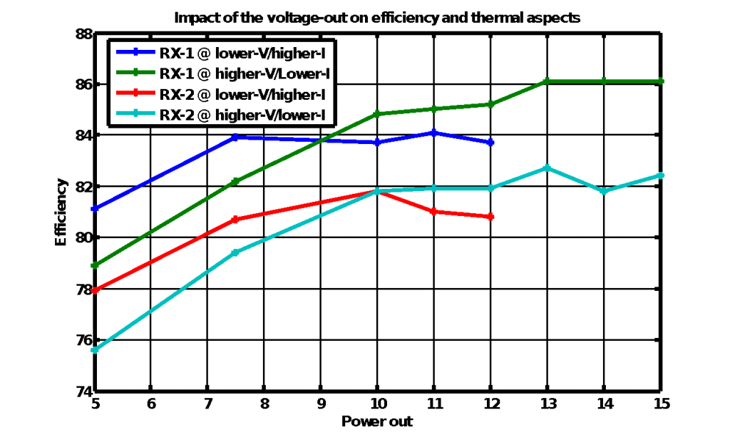
The I2R losses in the antennas generate heat. This can be minimized by reducing the current, IRX and/or by reducing the RAC(Coil). To reduce the current, one could need to use a higher voltage receiver Power Management IC (PMIC) topology. The RAC(Coil) can be reduced by using high-Q antennas that have a lower ESR (Equivalent Series Resistance). These two aspects result in better performance as seen in Fig. 3.

In general, for antennas for mobile devices, apart from being high-Q, they also need to be of small form factor and low profile (sometimes as thin as 250 um including shielding). Additional requirements of non-standard shape and integration of multiple antennas (for e.g. NFC) are often placed on the antenna designer to reduce overall cost and thickness. The requirements of thinness, flexible form factors, integration and robustness have resulted in flexible circuit antennas becoming the dominant technology for devices; printed antennas on a flex substrate are found in more than 75% of the handsets shipped (~ 200 million) in 2016 [9].
Wireless Power is a Thermal Problem
Most installed wireless power systems are designed to transfer a maximum of about 5W to the load (typically battery). With the advent of fast charge technologies, the need to charge at 10W and higher is imminent. In fact, devices from Samsung and Motorola are already shipping with the FastCharge feature.
With the move towards higher power levels, wireless charging in the consumer electronics domain will be viewed increasingly as a thermal problem, if not already, with the general electrical system architecture becoming quasi-commodity. The implication of the last statement is that thermal design will dominate the electrical design of the wireless charging system.
Consider the following numerical example: An inductive system delivering 5W operating at 75% efficiency dissipates about 1.67W, while a system that delivers 10W operating at 82% efficiency and dissipates about 2.19W. Alternatively, the 10W system will need to operate at nearly 86% (a 15% increase) to dissipate the same amount as a 5W system. If the system is broken down into 3 parts as shown in Fig. 1, assuming identical efficiencies, each block will need to operate at 95% efficiency. Now, assuming a typical inductive system with QTx ~ 80, QRx ~ 15, and coupling ~ 0.62, results in antenna to antenna efficiency of ~ 91%. To obtain the 86% efficiency, this will require the other two blocks for this inductive system to operate at 97%!
In other words, we are pushing physics in terms of efficiency. We saw a similar example in the previous section for a 15W system where a 4% efficiency drop to 82% resulted in an additional 850 mW dissipated power. To put things in perspective, a typical WiFi modem in a handset consumes ~ 700 mW power, the handset drains about 320 mW power during an audio playback, and about 1.05 W in a 1-minute phone call with display off [11, 12].
Solving the Thermal Problem
The fundamental problems that product engineers think about are, first, how do we minimize heat generation, and second, once heat is generated, how do we spread it quickly from the main heat centers to prevent localized heating.
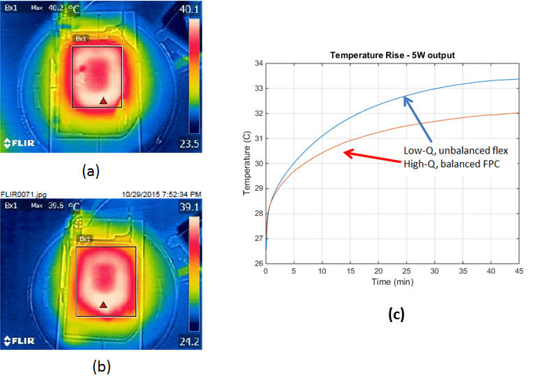
Per the assertion in the previous section regarding the quasi-commoditization of the system architecture, the answer to the first question is “relatively” straightforward, i.e. choose the best components (IC’s and antennas) and ensure optimum implementation for the use cases being considered. For example, consider Figures 5 a, b and c; they present the thermal data using two systems that are identical in every respect, except in the design and the technology of the wireless power antenna. The antenna in Fig. 5b offers a higher Q (by about 20%) that results in an efficiency improvement by ~2 percent, and runs about 1.3 degrees cooler. Incidentally, the higher-Q antenna is also cheaper to fabricate since it uses a standard flexible circuit technology unlike the unbalanced FPC fabrication utilized for the coil in Fig. 5a.

The challenge is further exacerbated as devices become thinner; batteries get larger thereby reducing the space available for the components associated with wireless charging. By far the largest component of the wireless charging system is the antenna.
It should be noted that for smaller devices such as wearables, significantly lower power dissipation will be allowable before temperatures start touching the magical limit of 45 degrees C [6, 8].
Therefore, there is a high demand for ultra-thin antennas that deliver maximum performance. Often, a heat spreader material is placed, for example, between the antenna and the backcover of the device. These heat spreaders demonstrate an anisotropic thermal conductivity, i.e. they conduct heat more easily in the xy direction than in the z-direction [13].
The use of Phase Change Materials (PCM) and heat pipes is also a way to direct heat away from thermal sources. Samsung engineers implemented this in the Galaxy 7 [14]. While the primary purpose of this is to drive heat away from the power intensive Application Processor, it is conceivable that the concept could be applied to the wireless charging coil, especially for higher power solutions.
Concluding Remarks
This article provides a high-level discussion on the thermal effects of wireless charging on consumer electronics devices. A key takeaway is that the wireless charging problem, at least in the realm of near field magnetic induction, is fast becoming a predominantly thermal problem. For starters, the highest performing components will be required and magnetics design will need to be optimized for maximum coupling (k) and efficiency (Q); however, the design will need to be driven from a thermal perspective. This need will become more pronounced as the devices become thinner, have more components, and house large batteries. Further, components that have worked in the past will not work in the future – higher power densities will warrant improvements in antenna materials and fabrication technology, magnetic shielding materials and heat spreaders.
The author would also like to point out that, while efficiency is an important metric, it should be considered in concert with the desired consumer use case, technology robustness and cost, and most importantly, the thermal increments in the devices. It is possible that a system operating at a lower efficiency leaves a lower thermal footprint on the device than the higher efficiency device because the product implementation and/or thermal design.
Acknowledgements
The author would like to thank Pavel Shostak, for his help with the data, and Michael Gotlieb, Jacob Babcock, Bob Giometti and Ryan Grieves for their inputs on the article.
REFERENCES
- http://www.mediapost.com/publications/article/291162/consumers-like-want-wireless-charging.html
- https://www.wirelessdesignmag.com/article/2016/10/wireless-charging-standards-reading-tarot-cards
- http://www.anandtech.com/show/9130/wireless-charging-standards-in-mobile
- https://news.samsung.com/global/faces-of-innovation-galaxy-s7-s7-edge-how-we-created-the-cooling-system-in-the-galaxy-s7-and-s7-edge
- S.P. Gurrum et al, “Generic Thermal Analysis for Phone and Tablet Systems”, 62nd IEEE Electronics Components and Technology Conference (ECTC), 2012
- https://www.qualcomm.com/news/onq/2013/10/09/thermal-efficiency-snapdragon-processors-under-screen-and-behind-trends
- http://www.emcchicago.org/pres/ti0415.pdf
- https://www.wirelesspowerconsortium.com/blog/97/wireless-charging-in-automotive-that-is-here-and-now
- https://www.cnet.com/news/dell-laptops-coming-soon-with-witricity-wireless-charging/
- David Green (IHS Markit), “The Growing Reach of Wireless Power”, presentation at the Wireless Power Summit, Seattle, Nov 2016
- “Characteristics of Rechargeable Batteries”, TI Literature number SNVA533
- http://www.forbes.com/sites/christopherhelman/2013/09/07/how-much-energy-does-your-iphone-and-other-devices-use-and-what-to-do-about-it/#3766ad03228e
- https://developer.qualcomm.com/blog/mobile-apps-and-power-consumption-basics-part-1
- A. Carroll, G. Heiser, “An Analysis of Power Consumption in a Smart Phone”, Proceedings of the 2010 USENIX conference on USENIX annual technical conference, p.21-21, June 23-25, 2010, Boston, MA
- M. Smalc et al, “Thermal Performance of Natural Graphite Heat Spreaders”, Proceedings of IPACK2005, July 2005
Editor’s Note:
Electronics Cooling featured some results of Dr. Vinit Singh’s PhD dissertation work in an earlier article “Thermal Management in Body-Embedded Electronics” published in December 2016.


