INTRODUCTION
Militaries continue to expand their use of electronics in harsh environments while preserving an absolute minimal risk of failure. In this regard, effort spent early in the design process on concept development, parametric and trade-off studies, and simulation-driven design can yield amplified benefits in terms of product performance and reliability, reduced development costs, shorter overall design schedules, and minimized redesign iterations. This article describes a portion of the thermal management development process and highlights a few design elements of an electronics unit that is part of a deployed defense system.
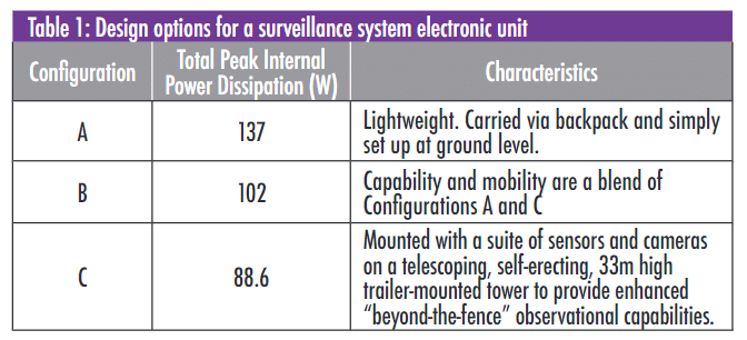
The electronics unit under consideration is part of a surveillance system that detects hostile troop movements at long distances. The unit is used in three system configurations that are tailored for the expeditionary setting.and the selection of sensors desired. The three variants (A, B, & C) of the electronics unit are identical except in how they are used and physically mounted, as shown in Table 1. Due to the different combination of sensors and cameras selected, each configuration dissipates a different amount of power and has a different orientation relative to gravity.
The functional design objective for the electronics unit was to develop a Versa Module Eurocard (VME) enclosure/chassis that would integrate the Intelligence/Surveillance/Reconnaissance (ISR) sensor data into a single Ethernet line. The unit is tasked with video processing, sensor input/output signal conditioning and processing, and sensor/camera power distribution and control. The unit utilizes both Commercial-Off-The-Shelf (COTS) and custom-designed Circuit Card Assembly (CCAs). Because of the high-mobility requirements, the size and weight (13.6 kg, max.) is an imposed design constraint.
Exterior views of the electronic unit are shown in Figure 1. The nominal outside dimensions of the unit are 27.3 cm wide x 21.6cm high x 27.9 cm long.
Inside, there are four VME CCAs: a custom relay CCA and three COTS CCAs that support I/O, Video Encoding, and Ethernet functions. These VME CCAs are mounted directly to slots in the chassis side walls. A power supply CCA utilizes an assortment of DC-DC converters and filters that are mounted directly to the chassis bottom panel. The chassis is fabricated from machined aluminum panels of Alloy 6063-T52 (thermal conductivity of 209W/mK). Fins are incorporated into the top, bottom, and side panels. The front and back panels are removable for servicing, or future configuration changes or upgrades.

The primary internal thermal loads, given in Table 1, are generated by the VME CCAs, and the DC-DC converters. The unit is subjected to an external solar thermal load, also. During maximum solar exposure [1], the units can be subjected to an additional 80.4 W for a two-hour time period. This period is considered sufficiently long to permit steady state thermal analysis to be employed.
The operating temperature limits, established by MIL-HDBK-310 [2], are a minimum and maximum ambient temperature of -32°C, and +49°C, respectively. The upper operating temperature limit applies concurrently with the solar radiation exposure. Other environmental considerations that contribute to the thermal management challenges include Electromagnetic Interference (EMI), altitude, rain, freezing rain, sand and dust, Nuclear/Biological/Chemical (NBC) exposure, shock, and vibration requirements as per MIL-STD-810 [3].
APPROACH
After initial hand calculations and spreadsheet analyses had been used to establish an initial design, a detailed thermal model was generated to perform CFD thermal analysis.
The CFD analysis included the effects of radiation with the painted aluminum chassis exterior assigned an emissivity of 0.92, while the interior chemical-conversion coated aluminum surfaces were assigned an emissivity of 0.20. The VME CCAs are conduction-cooled and rely on an intimate metal-to-metal interface to the chassis slots that is achieved using Wedge-lok connectors. An estimated Wedge-lok contact resistance of 1.1°C -cm 2/W [4] was incorporated into the analysis model. System temperature design requirements were established by the COTS VME CCAs (with maximum allowable card-edge continuous operating temperature of 85°C), the DC-DC converters (maximum allowable baseplate temperature of 100°C), and the Relays (maximum allowable case temperature of 100°C).
The initial CFD model was run for the three thermal load scenarios with and without solar loading. Initially, the maximum internal power dissipation was estimated to be 153 W. However, detailed evaluation of the electrical design eventually reduced the maximum load to 137 W. The initial results without solar loading indicated that the VME card edges could reach 92.4°C (7°C above their limit) while the DC-DC converters could reach 95.8°C (4°C below their limit).
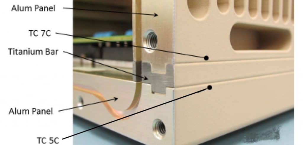
To reduce the temperature of the VME CCAs, the internal chassis design was modified to allow the fin lengths to be increased from 1.01 cm to 1.52 cm while retaining the same overall outer dimensions. In addition, since the DC-DC converters had some thermal margin, the chassis design was modified to inhibit heat from flowing from those devices to the side walls that cooled the VME CCAs. This was accomplished with a thermal dam formed of titanium (Grade 2) interposing bars placed between the chassis bottom panel and the two side panels.
Figure 2 shows a detail view of the dam and joint. The low thermal conductivity of the titanium of 16.4 W/mK helped to reduce the flow of heat from the floor to the walls. Other environmental constraints dictated that the dams be comprised of a stiff, high-strength, lower density, electrically-conductive material. While stainless steel might have met the thermal requirements for the dam material, it added excessive weight and was not used.
A detailed thermal analysis of the custom Relay CCA was conducted to ensure that the ten microprocessor-based Solid State Relays (SSR) mounted on the board did not exceed their maximum allowable case temperature of 100°C. The FEA model initially showed that case temperature would slightly be over this limit, so the PWB design was modified to increase the number of 4 oz copper thermal planes and copper-filled vias. The effective in-plane board thermal conductivity was determined by accounting for the copper layers while the impact of the vias on the thru-plane thermal conductivity was determined using Reference [5].
A 2.0 mm via pitch was selected for the thermal via arrays as the best compromise between thermal performance, circuit routing complexity and cost for this situation. These changes reduced the maximum case temperature to ~97°C as shown in Figure 3.

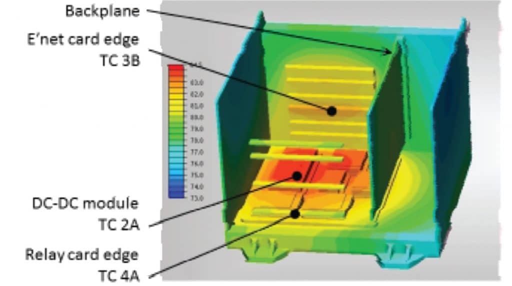
With these design changes implemented, along with other refinements CFD simulations of all but one of the six operational configurations (A, B and C, with and without solar loading) met requirements. The A configuration with maximum power dissipation 137 W along with the solar load did produce VME card edge temperatures that exceeded design requirements. However, the A configuration is limited to stationary ground level operation in which a solar shade can be easily employed to prevent direct solar loading, and thereby provide for satisfactory operation. Figure 4 provides a cut-away view of the temperature results from the analysis for 137 W peak internal thermal load without the solar load.
TEST
A comprehensive thermal survey was conducted to verify the thermal design and validate the simulations. The unit was instrumented with twenty-four Type T thermocouples (see Figs. 2, 3, & 4 for locations; TC4B is not shown) with maximum uncertainty of 1.5°C. To more realistically test worst-case conditions, the chamber blower was turned off at 1216 minutes.
This eliminated the unrealistic convection cooling that would otherwise result from the chamber blower, so that the unit would only be cooled by natural convection and radiation. Shutting off the blower caused all the unit temperatures to increase while the chamber temperature drooped due to heat loss to the surroundings. This droop in chamber ambient is directly seen in thermocouple 8°C in Figure 5.
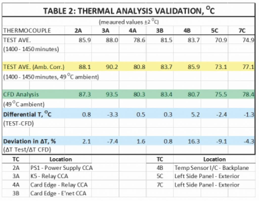
The unit temperatures stabilized ~ 3 hours after the chamber was turned off. Each temperature was averaged over a fifty-minute period from 1,400 minutes to 1,450 minutes while the average chamber ambient air temperature was 46.8°C. Average temperatures are shown in Table 1, which also shows ambient-corrected temperatures to reflect the chamber being 2.2°C below the 49°C requirement.
This table also shows the corresponding temperatures from the CFD analysis for the thermocouples. A comparison between the results of the test and simulation is given in that table. In general, the analysis agrees within ±5°C of the testing, which is a design objective [6].
Location 4B (the Temperature Sensor I/C mounted on the Backplane) is the only example of a test measurement more than 5°C different than predicted by CFD. This is thought to be due to the
CFD model having an unrealistic space above the backplane in that location. Simulations predicted that natural convection cells with flows as high as 5 cm/s would occur in this region. In reality, the air space between VME CCAs was less than 1.5 cm, which greatly inhibited induced air flow.
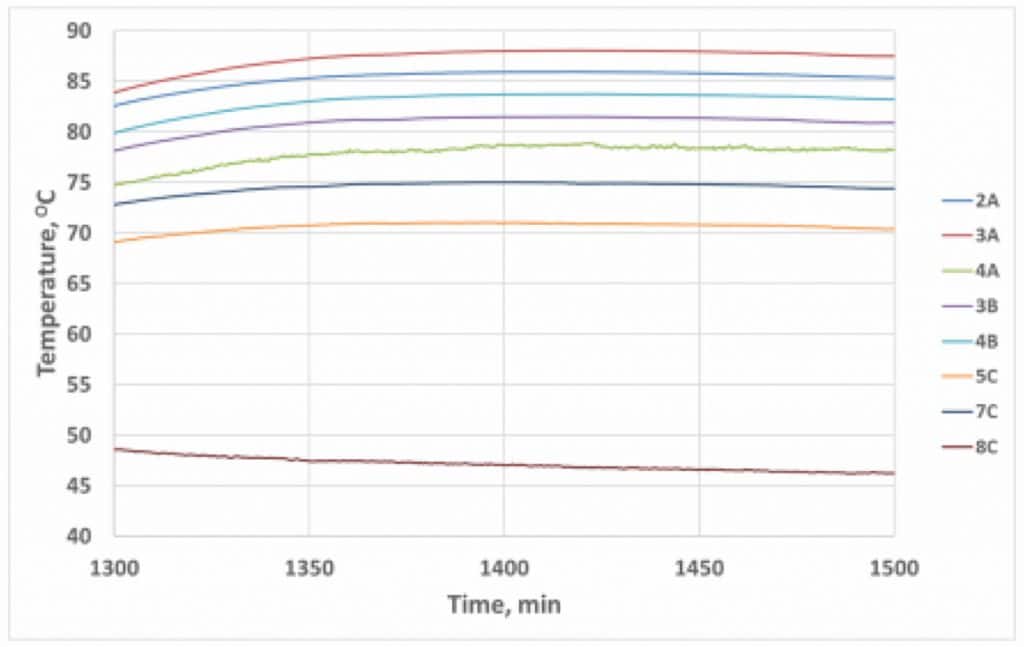
The temperature difference between thermocouple 5°C (on the chassis bottom panel immediately adjacent to the titanium bar, see Figure 2) and location 7°C (on the chassis side panel, immediately adjacent to the titanium bar) represent the temperature drop across the bar. While CFD predicted a ∆T of 2.9°C, the test found a ∆T of 4.0°C, which indicates that the thermal dam actually was somewhat more effective than had been predicted.
CONCLUSIONS
It was anticipated at the outset that there would be significant thermal management challenges to satisfactorily endure each of the environments and operating configurations required for this
system. The Thermal Survey confirmed that, although the COTS CCAs and DC-DC converters operate very close to their extreme limits, the operating temperatures are acceptable. Under the most severe, worst-case conditions, the COTS CCAs card edge temperatures are within approximately 2°C of their acceptable maximum continuous operating temperature and the DC-DC converters baseplate temperatures are within approximately 12°C of their acceptable maximum continuous operating temperature. The electronics unit has successfully passed comprehensive qualification testing and has since seen actual battleground deployment.
REFERENCES
[1] Army Regulation 70-38, “Research, Development, Test, and Evaluation of Materiel for Extreme Climatic Conditions,” Dept. of the Army, 1979.
[2] MIL-HDBK-310, “Global Climatic Data for Developing Military Products,” Dept. of Defense, 1997.
[3] MIL-STD-810, “Environmental Engineering Considerations and Laboratory Tests,”Dept of Defense, 2008.
[4] L.T. Yeh and R.C. Chu, “Thermal Management of Microelectronic Equipment,” ASME Press, 2002.
[5] B. Guenin, “Thermal Vias – A Packaging Engineer’s Best Friend,” Electronics Cooling, Aug., 2004.
[6] MIL-STD-2218, “Thermal Design, Analysis and Test Criteria for Airborne Electronic Equipment,” Dept. of Defense, 1992

