INTRODUCTION
In terrestrial or air-borne electrical and electronic systems, cooling requirements can be unsteady due to spikes in heat load, or changes in ambient conditions. Such an event results in a sharp rise in system temperature or temperature cycling thus possibly reducing the system reliability. In the electrical domain, fluctuations in voltage are managed by using an electrical capacitor that can be charged and discharged depending on the fluctuating environment. The lack of an effective thermal capacitor in the thermal domain has often led to designs that are oversized and focused on the peak worst-case scenario. Such a design strategy leads to an increase in system size and weight, which is typically undesired, especially for an airborne system. In this article, a thermal capacitor refers to a device capable of mitigating temperature rise or fluctuations by absorbing and releasing thermal energy.
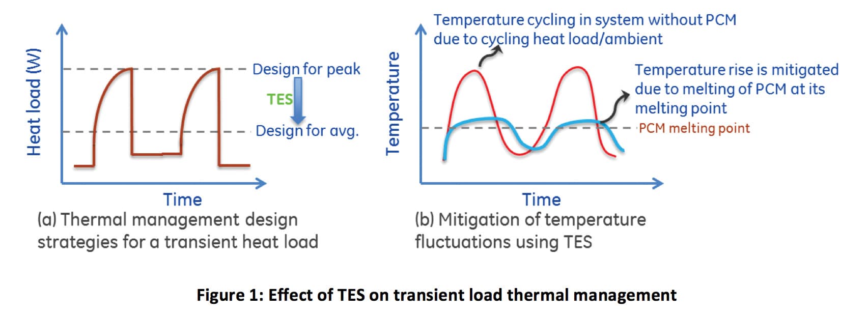
To optimize thermal designs such that they can be designed for an average heat load instead of a peak condition (Figure 1a), a thermal capacitor is needed. A key technique in the thermal domain that closely resembles an electrical capacitor is Thermal Energy Storage (TES). TES uses a phase change material (PCM), which upon absorption of heat from the system undergoes a solid-to-solid, solid-to-liquid, or liquid-to-gas phase transformation. Among these, solid-to-liquid phase change (melting of the PCM) is the most widely used TES system as it exhibits a lower volume expansion compared to a liquid-vapor phase change, and the latent heat of solid-to-solid phase change is typically lower than 100 kJ/kg [1] compared to latent heat of melting ranging between 200-300 kJ/kg for organic PCMs [2]. Phase change processes take place isothermally at their melting points, thus reducing the temperature rise of the systems that are thermally coupled to the PCM (Figure 1b).
In an aircraft, the electronic components are typically installed in designated avionics bays or equipment bays that are conditioned to maintain a temperature of approximately 55 °C. With increasing capabilities of the avionics, the heat load rejected to the environmental control system (ECS) increases. In a closely packed avionics bay the avionics chassis must have a good thermal design to prevent overheating or require excessive cooling air [3]. Additionally, avionics systems could also undergo transients in ambient temperature (potential increase up to 70 °C from steady state conditions) or loss of air cooling, arising from scenarios such as a stranded aircraft on a tarmac or an engine failure.
Adequately designed TES systems could, by delaying temperature rise, play an important role in providing additional time for the reliable operation of avionics without compromising functionality. In the absence of TES systems, typical strategies involve downclocking the computational systems to reduce temperature rise at the cost of reduced system capability.
A TES system typically consists of a hermetic enclosure which contains the PCM. One of the functions of the enclosure is to transport heat into the PCM material. An ideal thermal capacitor/ TES system has an infinite energy storage capacity and a zero thermal resistance from exterior walls to the PCM material. However, in reality a TES system is rendered less effective due to the poor thermal conductivity of organic or inorganic PCM (0.2-0.5 W/m-K) and the distance over which heat is conducted from exterior to the center of PCM, depending on the form factor of the PCM enclosure. While many studies have shown that thermal conductivity of PCMs could be improved by using additives and fillers, such as graphite and carbon micro structures [4-7], to approximately 2-5 W/m-K, the thermal resistance benefit is still modest and the possible complexity of using fillers could prove prohibitive for productization.
The formulation for 1-D thermal resistance of a solid wall, based on the Fourier’s law of conduction, is given in Equation (1). From this equation, it can be inferred that besides increasing the thermal conductivity (kpcm), the thermal resistance could be decreased by lowering the distance (L) and/or by increasing the surface area (A) over which heat is conducted. Although thermal resistance applies only for a steady state system, the phase change process in a TES system could be considered as a quasi-steady state process.
(1)
Where L = Length of heat conduction through the PCM (m)
A = Surface area (m2)
kpcm = Thermal conductivity of PCM (W/m-K)
Rcond = Conduction thermal resistance through the PCM (°C/W)
Th = Temperature of heated surface (°C)
TPCM = Temperature of PCM (°C)
This article focuses on the development of a modular, scalable TES enclosure with a low thermal resistance (0.1 °C/W) achieved by minimizing the ratio of L⁄A.
DEVELOPMENT OF A 3U THERMAL ENERGY STORAGE CARD
The aforementioned design principle of minimizing “L/A” was used in the development of a prototype 3U (a standard form factor of an electronic card) TES card for use in a Line Replaceable Unit (LRU) avionics chassis. An LRU chassis has a number of slots in which electronics cards can be installed. If the chassis slots are not completely filled, one or more TES cards can be added in the available slots to increase the thermal capacitance of the system. Although this version focused on development of a TES system for avionics, the designed thermal capacitor, reported in this study, has broad applicability for any application that has a varying duty cycle (i.e. high peak loads or boundary conditions that limit the design).
A device that closely resembles the required combination of high surface area and small conduction distance is a parallel plate electrical capacitor where the electrical capacitance is directly proportional to the surface area and inversely proportional to plate spacing. Analogous to a parallel plate capacitor, a structure was developed that consists of a parallel network of heat pipes that extend from the walls of the TES enclosure at one end, and attached to tightly spaced parallel plate fins embedded in the PCM at the other end.
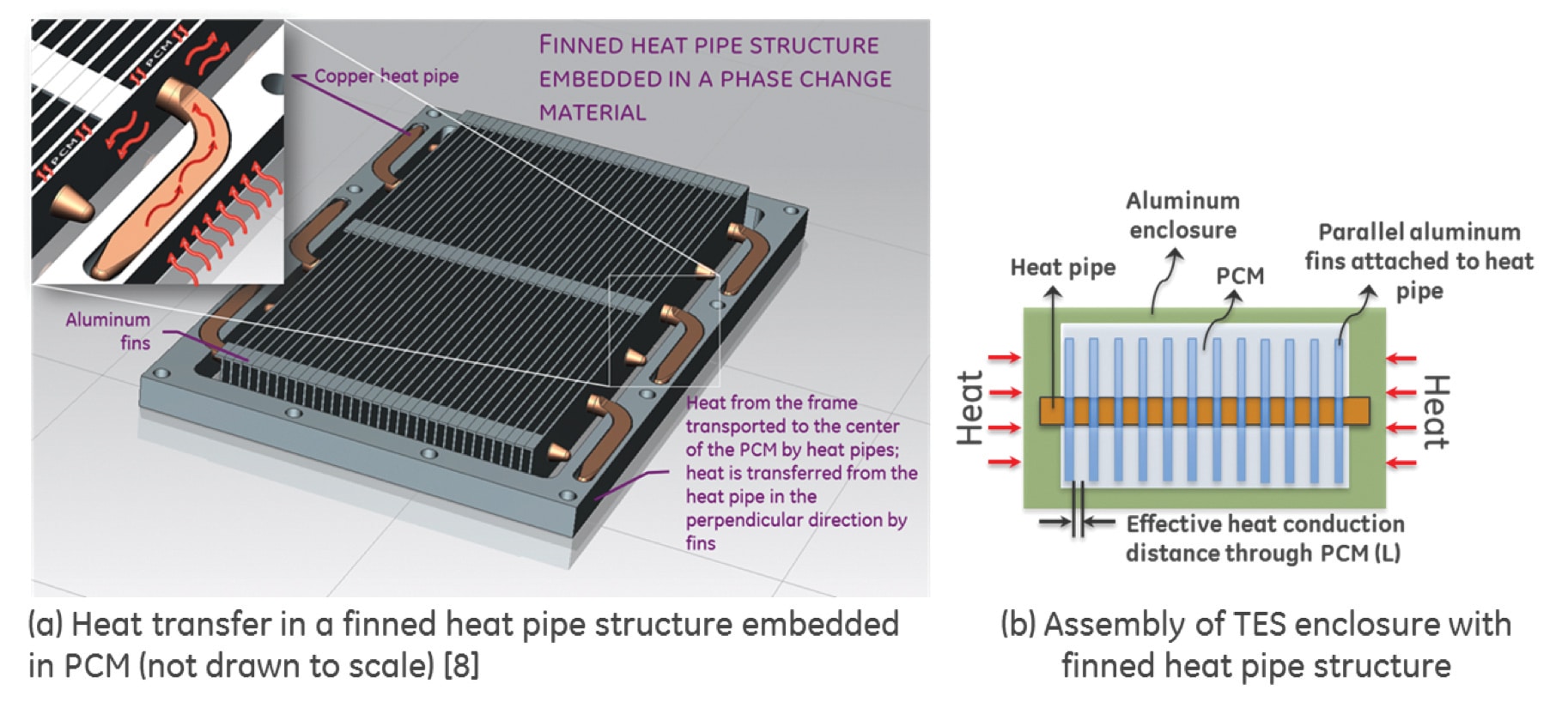
These heat pipes form the primary low thermal resistance conduction path from the walls to the center from where heat is distributed laterally in the aluminum fins as shown in Figure 2. Such a structure results in a congruent isothermal melting process over the volume of the enclosure while maximizing the surface area and porosity for heat transfer and storage, respectively. A schematic layout of the finned heat pipe structure (FHP) to explain the nomenclature involved in the design is shown in Figure 3.
An attractive feature of the finned heat pipe structure (FHP) developed is the adaptability and scalability to other applications owing to its simple architecture. For a given application with its energy storage or temperature stability requirements, the design of FHP structure involves optimization of the key parameters listed below to achieve a target thermal resistance:
- number of heat pipes (nhp)
- spacing between heat pipe (shp)
- number of fins (nf)
- fin spacing (sf)
- PCM material melt temparture (Tmelt,pcm)
The structure shown in Figure 3 was optimized to result in a thermal resistance < 0.1 °C/W (defined as shown in Equation 1) measured at the end of phase change, from exterior side wall to PCM center. Optimization of the FHP structure for the target application will be part of a separate study and hence not reported in this article. The optimized parameters are shown in Figure 3b. The resulting porosity (volume available for PCM in the enclosure) of the optimized finned heat pipe structure is 78%. This is comparable to the porosity of foam structures which could be up to 90-95% [9].
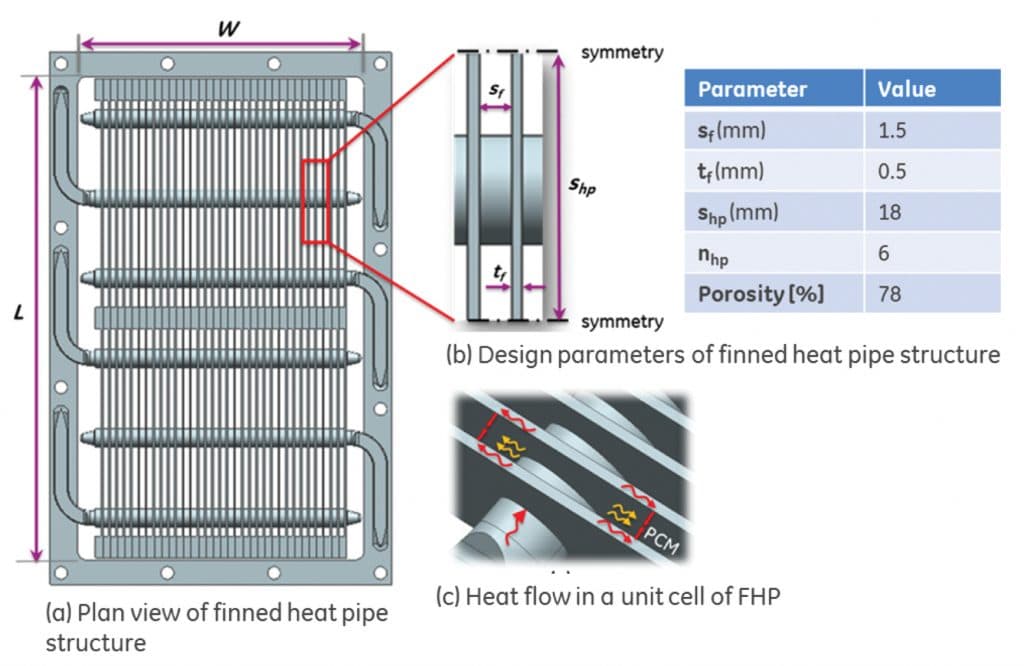
For a PCM enclosed within tightly spaced fins, convection effects of melted PCM are negligible as the buoyancy forces in such thin spaces are not sufficient to overcome the viscous forces. This can be expressed non-dimensionally using Rayleigh number (Ra). The critical Rayleigh number (Racr) over which buoyancy dominates is 1708 [10]. In comparison, the fin spacing of 1.6 mm results in a Ra lower than 1708, indicating that the dominant mode of heat transfer is conduction. This allows for a simpler 1-D/2-D conduction model to be used in the design of finned heat pipe structure depicted in this study.
It should be noted that the benefit of a thermal enhancement structure, such as a finned heat pipe, is reduced in a thin spreadout PCM volume placed on a thermally conductive surface owing to the small conduction lengths in the direction of heat transfer. In the current study, with heat application at the sides, the effective conduction length without any embedded structure is one-half of the width of enclosure, which is 42 mm. With the addition of finned heat pipe structure the effective conduction length has been reduced to 0.8 mm, which is one-half of the fin spacing (52.5x improvement).
EXPERIMENTAL EVALUATION OF THE FINNED HEAT PIPE STRUCTURE
A prototype 3U TES card with the aforementioned FHP parameters was developed for experimental performance validation. An experiment was devised to quantify the benefit of the FHP structure. A test system was developed to add heat to the system at the siderails (similar to an LRU chassis) while measuring temperature of the heaters and PCM during the process of heating.
To evaluate the effect of the finned heat pipe structure versus a system that is just filled with plain PCM, a TES enclosure without the finned heat pipe structure was also constructed as baseline. In all experiments, applied heat input was varied between 15 to 45 W and the transient temperature response of the system was recorded. Results reported in this article are limited to melting of the PCM and results corresponding to PCM re-solidification will be reported in a separate study.
Transient temperature profiles of the PCM and heated enclosure sides with and without the FHP structure heated at 30W are shown in Figure 4. In the absence of the finned heat pipe structure, i.e. baseline, the temperature of the heater continued to rise even after the PCM started melting at 69 °C (red dotted line). It was also noticed that the difference in temperature between the heated sides and the PCM center (blue dotted line) was more than 10 °C at the completion of melting. This is mainly due to the aforementioned high thermal resistance of the phase change material arising from the poor thermal conductivity and the longer distance of heat transport (42 mm).
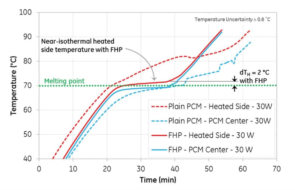
In the case where the finned heat pipe structure was employed, once the melting point of PCM was reached, the heater temperature (red solid line) was observed to be near-isothermal and the observed temperature difference between the heated sides and the PCM at the center (blue solid line) was less than 2 °C. This result is attributed to the significant lower thermal resistance resulting from the lower conduction distance through the PCM between the fins (0.8 mm).
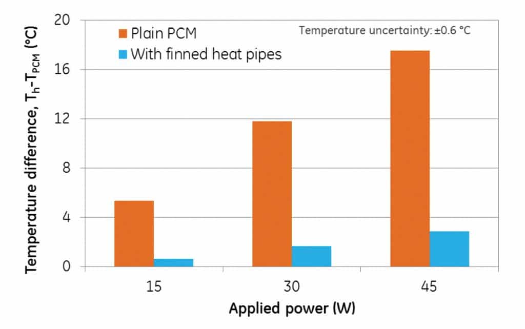
In Figure 5, the effect of applied power on the reduction in temperature difference between the heater and PCM center due to FHP is illustrated. At 45 W, the temperature rise of heater above the melting point of PCM is 3 °C with FHP and 18 °C without the FHP, further demonstrating the improved near-isothermal phase change performance of the prototype at all tested conditions compared to the baseline. The low thermal resistance of the designed architecture not only aids in faster charging of PCM, but also faster discharging of heat, thus enabling the use of the designed TES system for higher frequency of transient heat pulses.
FIGURE OF MERIT AND COMPARISON WITH LITERATURE
An ideal TES system possesses an infinite energy storage capacity and a low thermal resistance (low temperature rise of the heated system) which enables rapid charging and discharging. Based on these characteristics, an effective heat capacitance (Ceff) during phase change is defined, as shown in Equation (2), which has to be maximized for a TES system to be effective
(2)
where Ceff = System thermal capacitance (kJ/kg-K))
Q = Heat supplied (W)
dt = Time between start and end of melting process
(s) m = Mass (kg)
dT = Temperature difference between completion and beginning of PCM melting process (°C); subscript ‘H’ and ‘PCM’ represent the temperature rise of heater and PCM during the phase change respectively
To illustrate the importance of the surface area to volume ratio, known as the specific surface area (β), Equation 2 can be re-arranged to give:
(3)
where q” = Heat flux (W/m2 )
Vtot = Total volume (m3 )
ε = Porosity (-)
β = Specific surface area = As ⁄ Vtot (m-1)
It can be inferred that increasing the surface area to volume area ratio will increase the effective thermal capacitance or the storage capacity. In the current design of FHP, the specific surface area is approximately 910 m-1 which is comparable to finned structures and matrices used in many compact heat exchangers [11].
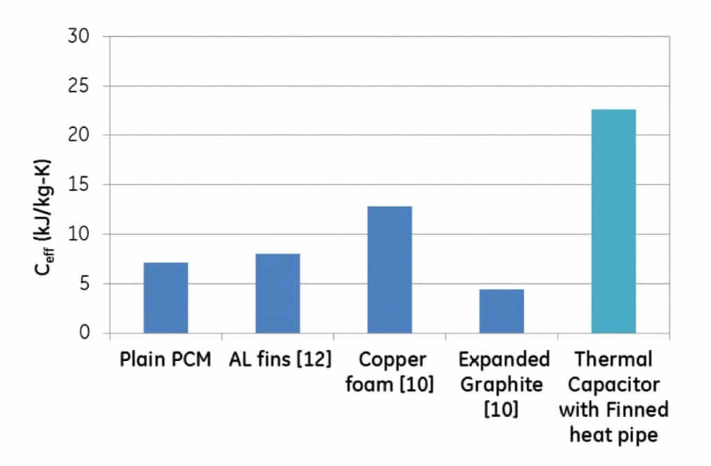
Figure 6 represents the effective specific heat of the thermal energy storage system compared against other techniques used to improve the thermal resistance of PCM. The higher capacitance of the finned heat pipe structure is directly a result of the low temperature rise of the heater over the melting point (2 °C at 30 W). It must be noted that comparison with literature was only made with systems that do not have a thin form factor in the direction of heat transfer as the role of thermal enhancement structure in thin PCM volumes are limited owing to the inherent small conduction lengths.
CONCLUSION
An effective thermal capacitor is developed that minimizes conduction length through the PCM by more than 50 times and maximizes surface area by the use of a finned heat pipe structure embedded in the PCM. The structure can be engineered to yield desired temperature rise and porosity specifications for most applications with conventional manufacturing techniques. A unique aspect of the thermal capacitor design is that it is modular such that it can be scaled up to larger volumes, yet still providing a low thermal resistance from walls to PCM. The concept of such thermal capacitor was demonstrated by evaluating the performance of a 3U thermal energy storage card for an LRU avionics system.
REFERENCES
[1] Ahmet Sari, Cemil Alkan, Alper Biçer, Ali Karaipekli, “Synthesis and thermal energy storage characteristics of polystyrene-graft-palmitic acid copolymers as solid–solid phase change materials”, Solar Energy Materials and Solar Cells 95(12), pp. 3195–3201, 2011.
[2] Atul Sharma, VV Tyagi, CR Chen, and D Buddhi, “Review on thermal energy storage with phase change materials and applications,” Renewable and Sustainable energy reviews, vol. 13, no. 2, pp. 318-345, 2009.
[3] Ian Moir and Allan Seabridge, “Aircraft systems: mechanical, electrical and avionics subsystems integration”, John Wiley \& Sons, vol. 21., 2008.
[4] Randy D. Weinstein, Thomas C. Kopec, Amy S. Fleischer, Elizabeth D’Addio, and Carol A. Bessel. “The experimental exploration of embedding phase change materials with graphite nanofibers for the thermal management of electronics”, Journal of Heat Transfer 130, no. 4, 2008.
[5] Omar Sanusi, Ronald Warzoha, and Amy S Fleischer, “Energy storage and solidification of paraffin phase change material embedded with graphite nanofibers,” International Journal of Heat and Mass Transfer, vol. 54, no. 19, pp. 4429-4436, 2011.
[6] Jun Fukai, Yuichi Hamada, Yoshio Morozumi, and Osamu Miyatake, “Effect of carbon-fiber brushes on conductive heat transfer in phase change materials,” International Journal of Heat and Mass Transfer, vol. 45, no. 24, pp. 4781-4792, 2002.
[7] F Frusteri, V Leonardi, S Vasta, and G Restuccia, “Thermal conductivity measurement of a PCM based storage system containing carbon fibers,” Applied thermal engineering, vol. 25, no. 11, pp. 1623-1633, 2005.
[8] Naveenan Thiagarajan, Hendrik Pieter DeBock, and William Gerstler, “Thermal Management System”, US Patent 9476651, 2016.
[9] Dan Zhou and Chang-Ying Zhao, “Experimental investigations on heat transfer in phase change materials (PCMs) embedded in porous materials,” Applied Thermal Engineering, vol. 31, no. 5, pp. 970-977, 2011.
[10] Frank P Incropera, Adrienne S Lavine, Theodore L Bergman, and David P DeWitt, “Fundamentals of heat and mass transfer”, Wiley, 2007.
[11] W.M. Kays and A.L. London, “Compact Heat Exchangers”, Natl. Press, Palo Alto, Calif., 1955.
[12] AJ Fossett, MT Maguire, AA Kudirka, FE Mills, and DA Brown, “Avionics passive cooling with microencapsulated phase change materials,” Journal of Electronic Packaging, vol. 120, no. 3, pp. 238-242, 1998.

