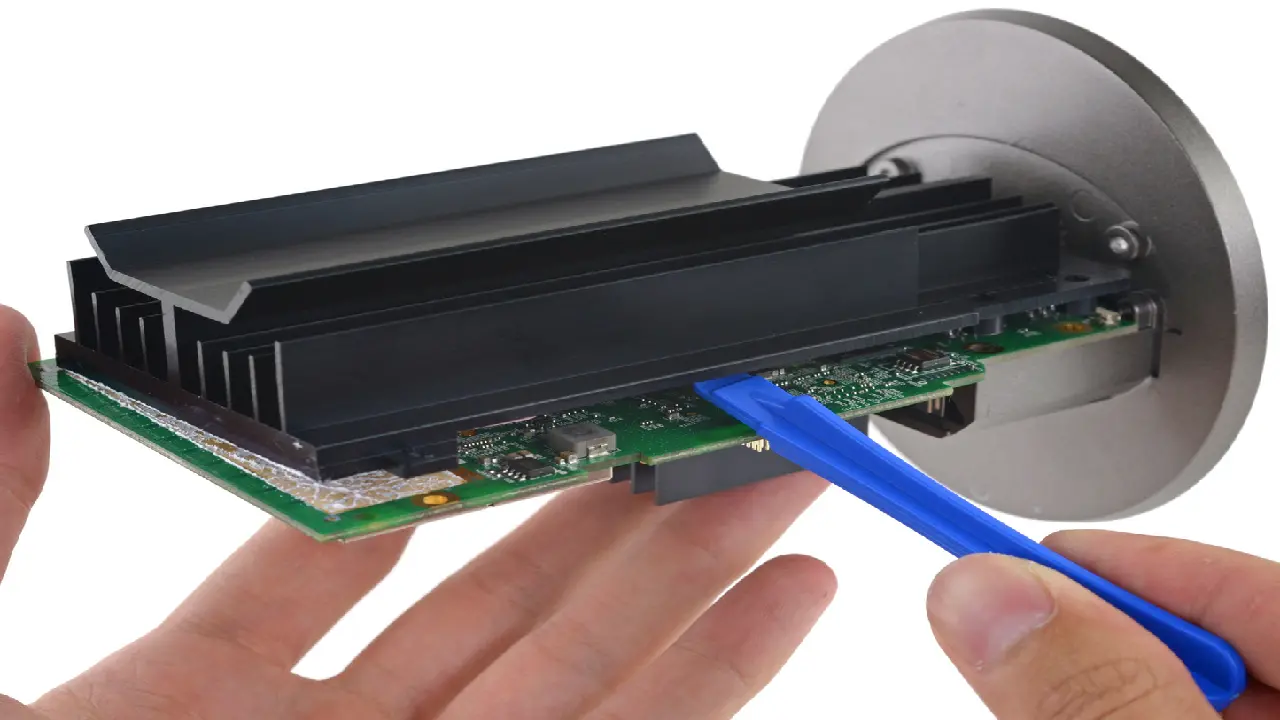
As Electronics Cooling engineers, we can say this unequivocally –the root cause of heat in electronics systems is power! Barring external and environmental influences, heat dissipation in electronic devices is an unavoidable side effect in any powered electronic device.
In this blog, we will take a look at the Internet of Things (IoT) Gateways, in particular Edge Gateways which connect to various “Things” that sense and report the data through these Gateways. And we will limit our discussions in this blog to Gateways that are deployed indoors, typically home IoT Gateways. These are typically Broadband Router and Gateway combinations without Cellular modems. Electronics Cooling will feature more articles later on thermal management of outdoor and ruggedized / industrial IoT Gateways. Furthermore, the evolution of IoT Gateways is headed in a direction where computing capability is increasingly being integrated in these Gateways in what is now popularly known as Edge or Fog Computing Nodes which take cloud computing literally to the edge; we will limit our discussion in this blog to Gateways with no or limited compute capability; just be clear, computing in this context is alluding to the support of applications hosted at the Edge Gateway. As described in our Editorial Calendar, Electronics Cooling will be releasing several thermal management miniguides throughout the year including one on the topic of Fog Computing which will also include coverage of Mobile Edge Computing (MEC).
What used to be simply known as embedded computing of yesteryears based on standards like PC/104, etc., is now a days supplemented with communication layer to make a completely self-contained connected product. Therefore, when it comes to discussing thermal management of IoT Gateways, the first thing to recognize is that we are dealing with thermal management of an embedded system with wired and/or wireless communication capabilities. Software has a primary impact on power consumption in an embedded system which is driven by the utility demands imposed on that embedded system. To reduce thermal dissipation, one needs to understand the power utilization in the device and develop new ways to aggressively reduce power in a dynamic manner.
Dealing with heat dissipation has long been the bottleneck in embedded systems design. To make matters worse, processing demands have increased in almost all categories of products, physical device sizes continue to shrink, and as if these were not enough, almost all embedded devices are passively cooled!
Software Thermal Management
Software-based Dynamic thermal management (DTM) techniques therefore form an essential piece of the runtime management stack in embedded systems. A good source to get started on DTM is this book “The Art of Software Thermal Management for Embedded Systems” (Electronics Cooling review coming later this year!) which provides an excellent background to software-driven thermal management. Dynamic power dissipation is modeled by:
P = C V2 f,
where P is power, C is capacitance, V is volts, and f is switching frequency. The book emphasizes that software-based thermal management is primarily dependent on the above equation on dynamic power dissipation.
Intel Joule for example includes help on installing heatsinks as well as a detailed thermal management overview which is based on:
- User safety through thermal ergonomics that control exposed surface temperatures.
- Prevent thermal runaway.
The Joule module provides two (BIOS-based) methods that work together to maintain a thermal target. One is temperature limit setting and the second is Run-time Average Power Limit (RAPL). The module provides hardware thermal controls that are intended to maintain operation within a set temperature range by adjusting processor speed or capping the maximum power consumption. This is accomplished by a combination of Thermal Control Circuit (TCC) and Power Limit 1 (PL1) which is based on RAPL. However, PL1 is a static limit of the maximum module power while TCC is below set point. When module temperature is above the TCC set point, the TCC function dynamically lowers PL1 until the TCC value returns below the set point.
The IoT Gateways
Note that there are contrarian views and opinions on the need for a home IoT Gateway, some arguing that a smart phone can manage most of the functions provided by a home IoT Gateway. Such opposite views not withstanding, broadband internet providers like Comcast are indeed integrating multi-protocol radios into cable modems/routers thereby augmenting its function to that of a full-fledged IoT Gateway.
Today, with the naysayers on the market potential of consumer IoT not withstanding, there is a bewildering array of choices for IoT Gateways. Gadgets from Intel for example include a series of Gateway solutions like the DK100 Series for Industrial and Energy, DK200 Series for Transportation and the DK300 Series for Industrial, Energy, and Transportation. On the consumer side, there are IoT Gateways available today from Amazon (yes, the Echo is now a days positioned as a IoT Hub!), Logitech, Google (OnHub), Motorola, etc., are some of the vendors to choose from.
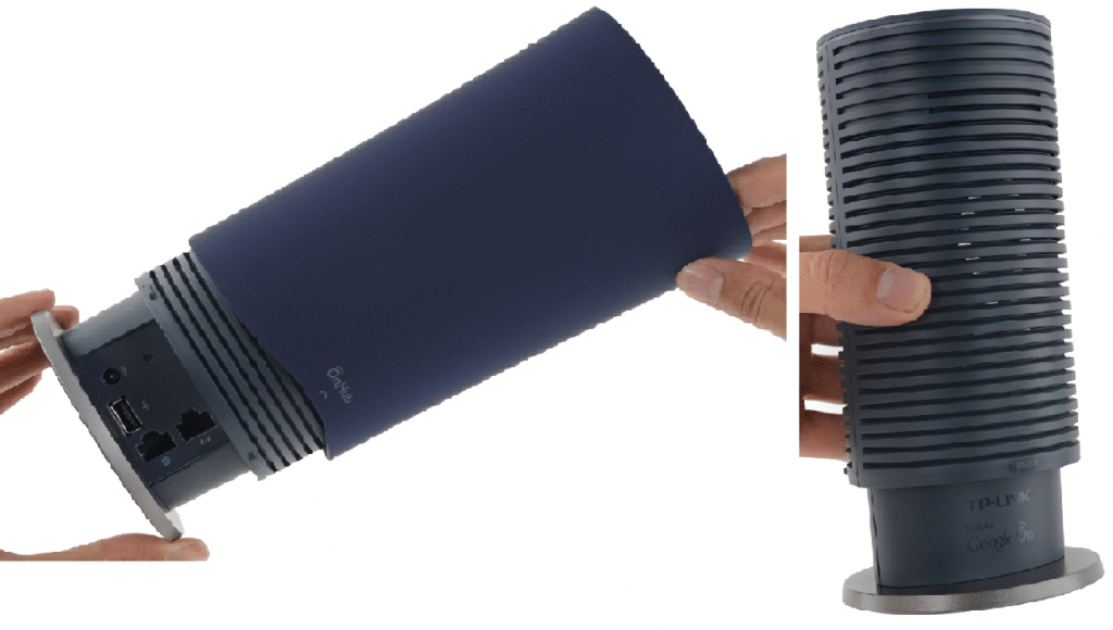
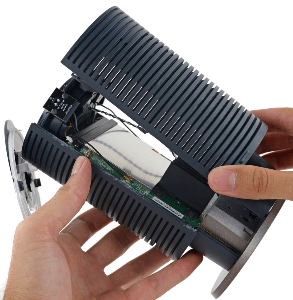
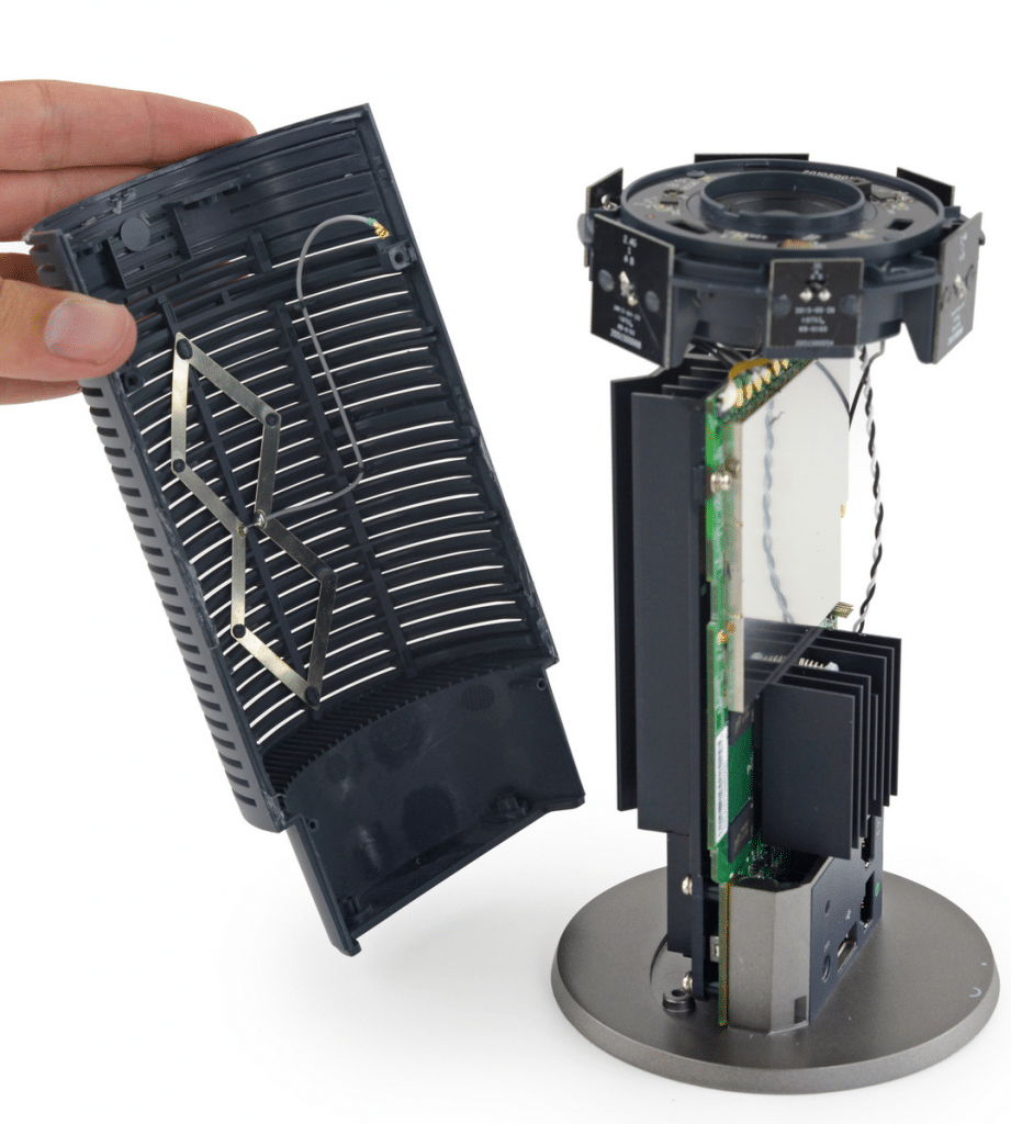
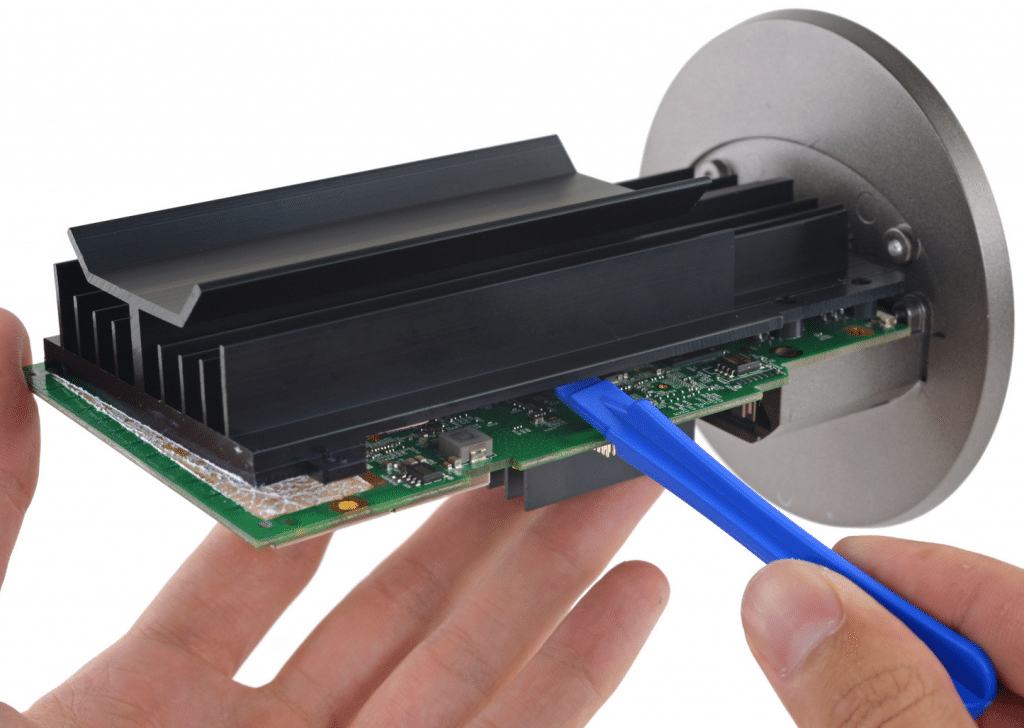
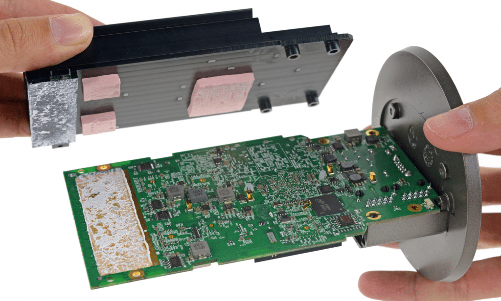
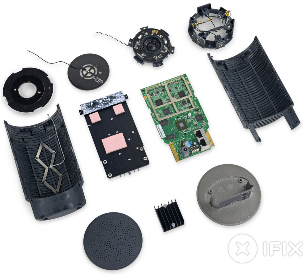
In the following paragraphs, we will present the thermal management approaches adopted in the Google OnHub product from a teardown.
Google’s OnHub router which comes in two versions promises a new robust way to Wi-Fi and Bluetooth connectivity with the following specs:
- Dual-core 1.4 GHz CPU
- 4 GB e-MMC flash storage
- IEEE 802.11 b/g/n/ac
- Dual band 2.4 GHz and 5 GHz 12-antenna array
- Congestion-sensing radio and antenna
- USB 3.0 port + Bluetooth 4.0
- 1 GB DDR3L RAM
One OnHub version’s teardown and the thermal design attributes thereof are presented in the following figures.
In closing, passively cooled embedded thermal hardware components and systems pose a unique challenge to thermal management. What we consider as thermally adequate with sufficient margins under static operating conditions may not be sufficient to address the reliability of the product. The thermal design has to meet the dynamic operating conditions of the device wherein it is not just the maximum temperature limits of the components, the number of cycles also figures prominently. Your comments are welcome!
