Co-authored by: Feng Zhou, Shailesh N. Joshi, Ercan M. Dede
Electronics Research Department, Toyota Research Institute of North America,
1555 Woodridge Ave., Ann Arbor, MI 48105, US
INTRODUCTION
In 2012, vehicle fuel-efficiency standards were announced that require all US cars and light trucks to reach 54.5 miles per gallon on average by model year 2025. As a result, automobile manufacturers are working to improve fuel efficiency in order to meet current and future fuel economy requirements plus emissions regulations. Vehicle fuel efficiency is logically related to the efficiency of the internal combustion engine. It has been estimated that the thermal efficiency of a modern internal combustion (IC) engine is limited to 20-40%, while approximately 60-70% of fuel energy is wasted in the form of heat.
RC FOR AUTOMOTIVE APPLICATION
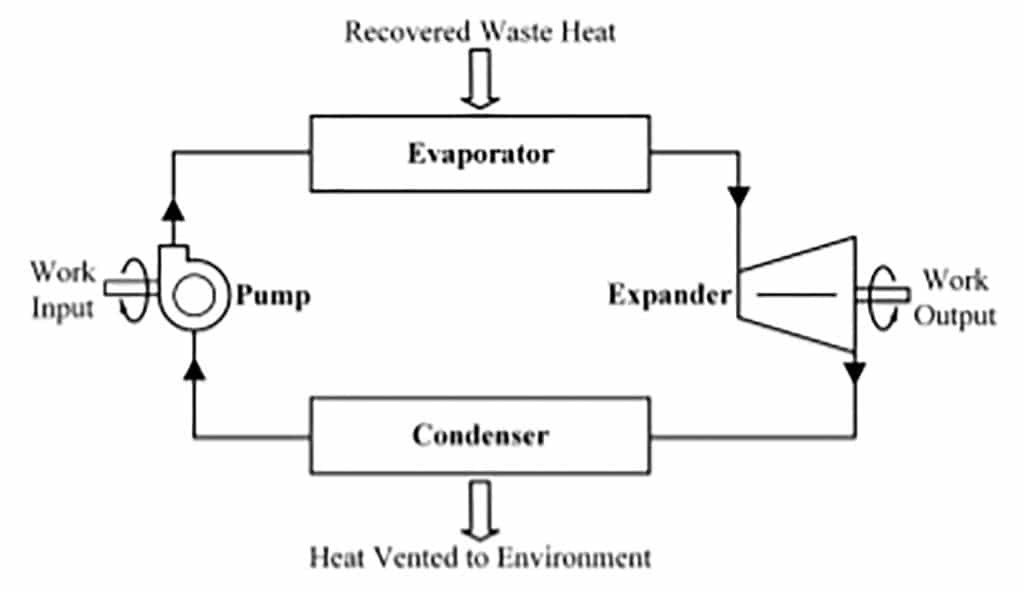
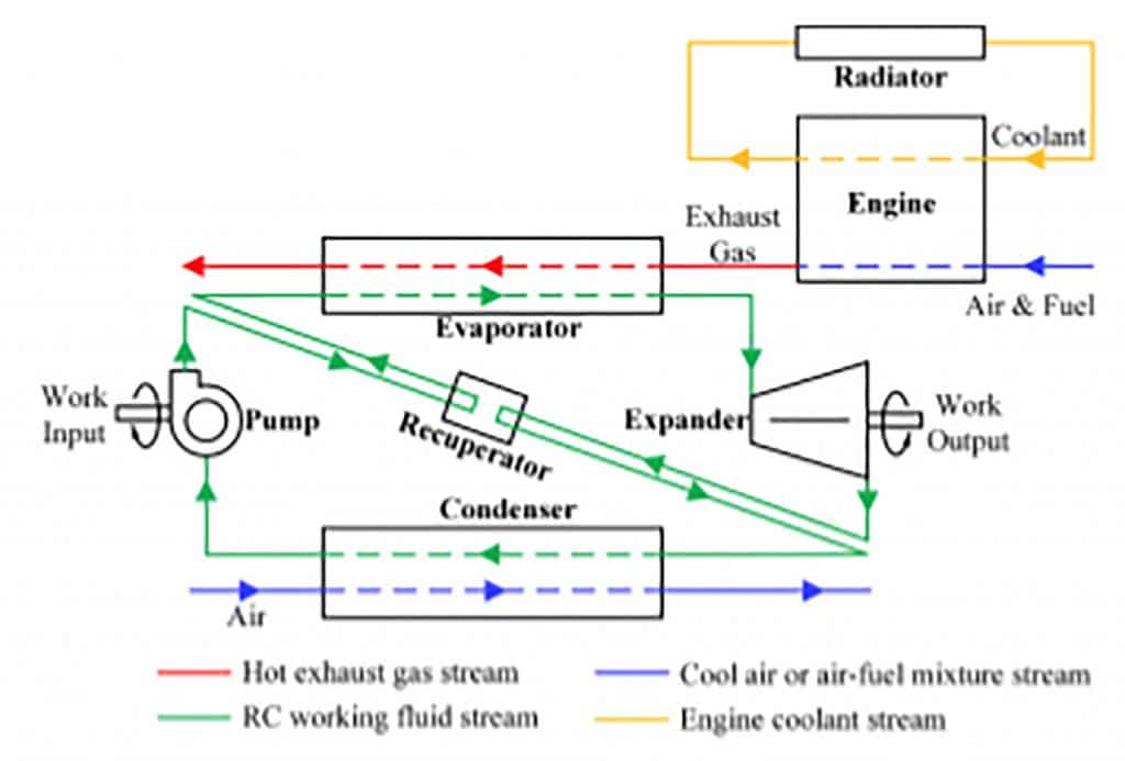
For automotive applications, the RC system is usually installed downstream of the catalyst to avoid negative influence on emission control by extending the time for the catalyst to reach light-off temperature at cold start and to utilize the extra energy produced by pollutant conversion within the catalyst. Heat sources on vehicles are different from other typical industrial heat sources, which are stable and have fewer space limitations for system implementation. The most common and simple RC system structure is shown in Figure 2, which utilizes the exhaust gas as the heat source to evaporate the working fluid.
Given the structure of a typical RC system, a question then arises regarding what is the best platform, e.g. vehicle type, for RC application. This is linked to another question of how to utilize the RC expander power output. Generally, there are two ways to use this recovered energy: 1) outputting the mechanical energy directly to the crank shaft or 2) combining the RC system with electrical generators to convert the mechanical energy into electricity. In the former method, a speed reduction gearbox might be required if the expander has a speed mismatch with the engine. For long-haul diesel trucks, there is more room in the engine compartment and the exhaust gas condition is more stable making these vehicles good candidates for the first RC power utilization method. For small passenger vehicles, the driving profile is not as stable leading to a fluctuating exhaust gas temperature. In this case, the second energy recovery method seems to be a more reasonable option, which requires an energy storage system to store the generated electricity. A hybrid vehicle (HV), which recovers some braking energy to increase the overall fuel efficiency, provides an ideal platform for transforming thermal energy to electricity, storing the electricity in batteries, and feeding this electricity back to the vehicle. By integrating a RC system into a HV to recover a portion of the waste energy, a hybrid vehicle will break the energy efficiency limit of the internal combustion engine to further boost fuel economy. Another advantage of applying a RC system to a HV is the relatively constant load conditions for the engine in a HV.
Regarding the integration of a RC system to a HV, the approach taken in minimizing the system complexity, weight, cost, and negative effects on existing components is balanced with maximizing the RC power output. Currently, as an add-on system to an existing vehicle, RC system integration might lead to important interactions and consequences, such as increased vehicle weight, increased engine back pressure, increased cooling demand of the vehicles, etc. Therefore, minimizing the interactions with existing vehicle components, and minimizing added RC components, is a main target for RC automotive application. Then, we must determine the best way to integrate the RC system into a HV for waste energy harvesting. Before answering this question, let’s switch gears to another topic: two-phase liquid cooling for power electronics.
TWO-PHASE POWER ELECTRONICS COOLING
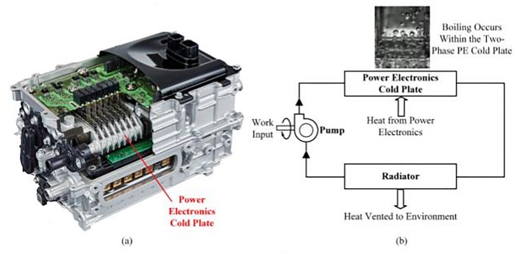
A transition away from silicon toward wide band-gap (WBG) semiconductor materials for power devices is expected in the next decade. For future electrified vehicles, the use of WBG devices, e.g. silicon carbide (SiC), gallium nitride (GaN), or diamond, in power electronics enables higher operational frequencies, lower switching losses, and high temperature, >200 °C, operation. However, the increasing demand of higher performance combined with smaller PE module size results in a continuously growing heat dissipation requirement, which challenges the limit of single-phase liquid cooling and makes two-phase (2j) liquid cooling [3, 4] attractive due to enhanced thermal performance.
SYSTEM CONCEPT & ANALYSIS
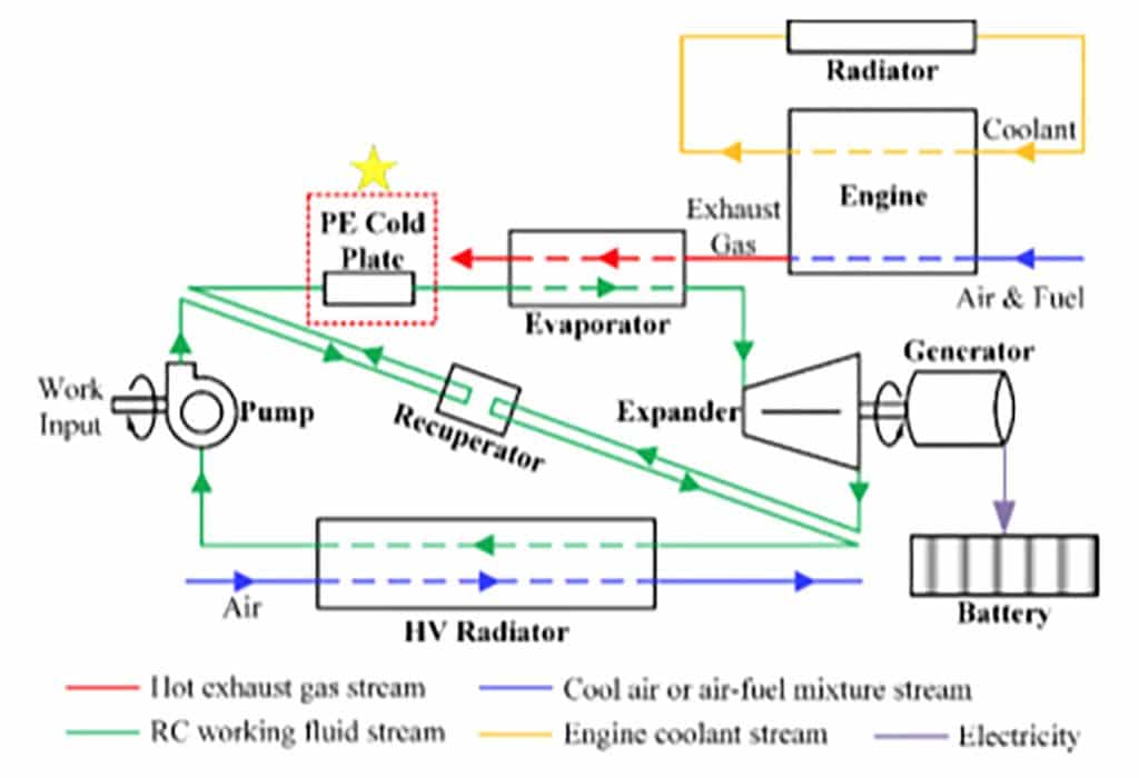
Figure 4 shows the concept of combining the RC system with the PE 2j cooling loop. Here, the pump, cold plate and HV radiator are three main components for the 2j cooling loop. To realize waste heat recovery, an evaporator and an expander are added to the system. A recuperator is also included in the current system, which is not necessary depending on the available space and capacity of the HV radiator. The waste heat from the engine coolant is not utilized in this system, but a liquid-to-liquid heat exchanger may be added to recover part of the coolant heat, considering the low boiling point of the refrigerant.
A thermodynamic model of the RC-2j system is developed on a commercial numerical modeling platform [6] to analyze the impact of the PE cold plate to the whole energy recovery system; a detailed sketch of the model is available in [1]. The model has six sub-models: 1) pump, 2) power electronics, 3) evaporator, 4) expander, 5) HV radiator, and 6) recuperator. The system working fluid and working conditions including assumed component efficiencies are summarized in [1]. The overall system coefficient of performance (COP) is evaluated as COP = Wexpander/Wpump, in which Wexpander is the work output of the expander and Wpump is the work consumed by the pump system.
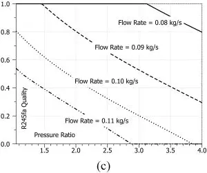
The results for the proposed RC-2j integrated system with recuperator are shown in Figure 6. For the current system with two-phase power electronics cooling, the vapor quality at the cold plate outlet (i.e. evaporator inlet) is an important parameter that requires dedicated control. If the flow rate is excessively low, all of the refrigerant flowing through the cold plate vaporizes, which might result in dryout of the heat exchange surface within the cold plate. The flow rate also cannot be excessively high otherwise the flow through the cold plate becomes single-phase, which lowers cooling performance.
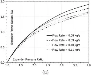
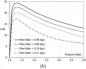
The power electronics is an additional heat source in the cycle, so higher refrigerant flow rates are necessary to avoid dryout. Therefore, for the current system structure, the studied flow rates include 0.08, 0.09, 0.10 and 0.11 kg/s. The variation of the expander power output, COP and cold plate outlet vapor quality follow the same trends shown in Figure 5. However, at the same flow rate (e.g. 0.08 kg/s), the power electronics module boosts the expander power output ~58% to 1.9 kW from 1.2 kW for the system without power electronics. The COP also increases ~20% from 20 to 24 since additional heat is recovered by the system. The impact of heat input from the power electronics to the waste heat recovery system is well demonstrated.
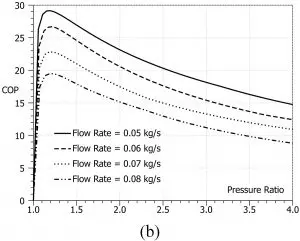
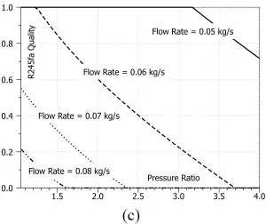
Figure 5: Expander power output, COP and evaporator inlet vapor quality as a function of expander pressure ratio for traditional RC system without PE cooling (structure as shown in Figure 2) [1].
Figure 6: Expander power output, COP and cold plate outlet vapor quality as a function of expander pressure ratio for the proposed RC-2j integrated system with recuperator as illustrated in Figure 4 [1].
CONCLUSIONS
Applying a RC system to a HV platform has great potential to further boost fuel economy to meet future emission requirements with system integration as one of the biggest hurdles. Nonetheless, a novel aspect of the RC-2j integrated system concept presented herein is that it not only keeps the HV power electronics cool at high efficiency, but also recovers more heat from the PE module for higher total system power output. It is found that the RC-2j integrated system boosted the expander power output ~58% from 1.2 kW to 1.9 kW under the same working conditions. The COP is also increased by 20% since an extra heat source is added to the system without consuming additional pumping power. Codesigning the RC system and HV power train in combination with other technologies, such as turbocharging or in-wheel motors, may drive the fuel efficiency of such vehicles to a higher level.
REFERENCES
- Zhou, F., Joshi, S.N., Rhote-Vaney, R., and Dede, E.M., A review and future application of Rankine Cycle to passenger vehicles for waste heat recovery. Renewable and Sustainable Energy Reviews, 2017. 75: p. 1008-1021.
- Saidur, R., Rezaei, M., Muzammil, W.K., Hassan, M.H., Paria, S., and Hasanuzzaman, M., Technologies to recover exhaust heat from internal combustion engines. Renewable and Sustainable Energy Reviews, 2012. 16(8): p. 5649-5659.
- Joshi, S.N. and Dede, E.M., Effect of sub-cooling on performance of a multi-jet two phase cooler with multi-scale porous surfaces. International Journal of Thermal Sciences, 2015. 87(0): p. 110-120.
- Zhou, F., Joshi, S.N., and Dede, E.M. Visualization of bubble behavior for jet impingement cooling with phase change. in Thermal and Thermomechanical Phenomena in Electronic Systems (ITherm), 2014 IEEE Intersociety Conference on. 2014.
- Newsroom, T.-U. 2016-2017 Toyota Prius PCU On the WWW. [Online]. Available: http://toyotanews.pressroom. toyota.com/. June 2017.
- Imagine.Lab, L., AMESim – Advanced Modeling Environment for Performing Simulations of Engineering Systems, http:// www.plm.automation.siemens.com/en_us/products/lms/ imagine-lab/amesim/. 2014.

