An earlier article in this column considered the problem of cooling electronic components in a closed box [1]. In outdoor applications for example, it may be necessary to totally seal the box to prevent exposure to airborne particulates, water droplets or other sub- stances in the air that could be injurious to the electronic components. In such an application, heat picked up by the air circulating over the electronic components within the box is rejected to outside air by means of an air-to-air heat exchanger mounted in one of the walls of the box. Such a heat exchanger may be as simple as two plate-fin heat sinks (or a heat sink with fins on both sides) mounted base to base in an opening in the wall of the box. Of course in such cases, the air that is cooling the electronics components will always be higher in temperature than the outside air being used for heat rejection from the box. If this does not provide a satisfactory cooling solution, an alternative that might be considered is augmentation with thermoelectric cooling (TE) modules sandwiched between the heat sinks as shown in Figure 1.
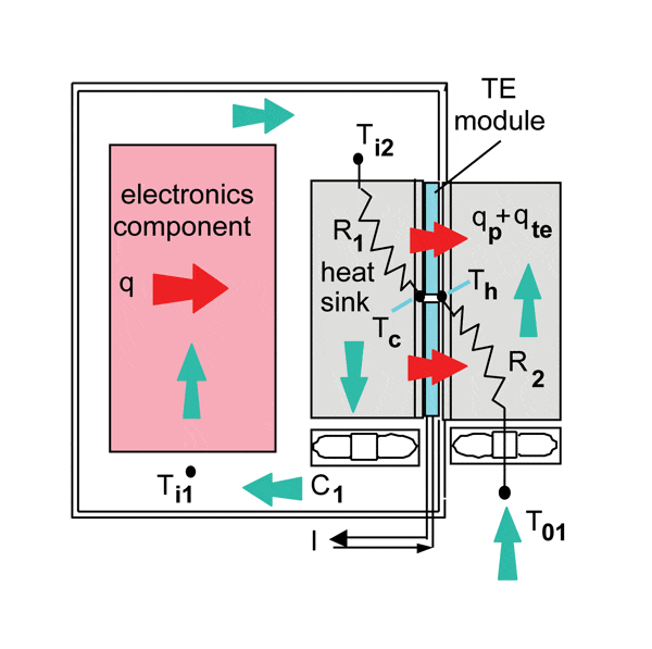
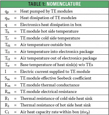
For those that are unfamiliar with TE modules, a thermoelectric cooler, sometimes called a Peltier cooler, is a solid-state heat pump that transfers heat from one side of the device to the other side depending on the direction of the applied electric current [2,3]. For example in Figure 1, electric current, I, may be applied to the thermoelectric modules such that the side in contact with the base of the heat sink within the box becomes cooler, thereby augmenting the transfer of heat from the air circulating within the box to the internal heat sink. The opposite side of the thermoelectric module becomes hotter and both the heat pumped by the thermoelectric cooler (qp), and the heat dissipated (qte) by the thermoelectric cooler in performing its heat pumping function, is transferred to outside cooling air via the external heat sink.
This article is intended to present to the reader, by example, a methodology to estimate the cooling air temperatures that can be achieved by thermoelectric augmentation. However, to illustrate the value of thermoelectric augmentation, we will first consider some equations to calculate the air temperature (Ti1) entering the portion of the box housing the electronic components without thermoelectric augmentation. Working from the air temperature (T01) outside the box to the temperature of the wall (Tw) of the box (or a base temperature common to the external and internal heat sinks) gives,
where q is the heat dissipation of the electronic components and R2 is the total thermal resistance of the external heat sink, neglecting the contribution of the rest of the wall. It should be noted that throughout this analysis and in the subsequent calculation examples, heat sink resistances, R1 and R2, are assumed to include both the convective part and any associated thermal interface resistance between the heat sinks and the wall or later in the article, the TE modules. The air temperature entering the internal heat sink passages is given by,
which, substituting in eq. (1) for Tw, gives
The temperature drop of the air passing through the internal heat sink is given by,
where C1 is the air heat capacity rate inside the box, given by the product of the mass flow rate, , and specific heat, cp, of the inside air cooling stream. So, the temperature, Ti1, of the cooling air entering the electronics compartment (without thermoelectric augmentation) becomes,
Now, we will proceed to determine the temperature of the air entering the electronics compartment when thermoelectric cooling augmentation is incorporated. To do this we must include equations to account for thermoeletric heat pumping and the heat dissipation of thermoelectric modules. In an earlier article, Luo [4] presented the following equation for heat pumping with a thermoelectric cooling module
and another equation for the corresponding TE heat dissipation
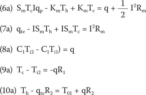
in terms of the TE parameters at the module as defined in the nomenclature and discussed by Luo [4]. It should be emphasized here that the temperatures, Th and Tc, in equations (6) and (7), as well as in equations (6a) and (7a) to follow, must be expressed in Kelvin temperature units (i.e. Kelvin temperature = Centigrade temperature + 273.16).
In addition to the above two thermoelectric equations we have the following heat transfer equations,
It should be noted here that under steady-state conditions heat load, q, in equations (8-10) is equal to the heat pumped, qp, by the thermoelectric cooler. Considering equations (8–10) together with thermo-electric equations (6) and (7) we have five linear algebraic equations. Given that we know or can assume values for q, R1, R2 , C1, Sm, Km, Rm and I, we are left with five unknown variables. The unknown variables are qte, Th, Tc, Ti2 and Ti1 (which is the variable we are really after). It is possible to solve these equations via algebraic substitution, as the author has done with the aid of software [5] capable of performing symbolic algebraic manipulation. However, the author found that the algebraic solution obtained for Ti1 by this method was so long (about two or three screen-widths) and so complex as to be of practically no value other than demonstrating that a solution could be obtained.
A method of practical utility is to solve these equations for numerical values using a matrix method as employed in an earlier article addressing the solution of a thermal resistance network [6]. To do this we first rearrange the equations (6-10) so that the unknown variables are on the left-hand side of the equation and the constant terms are on the right-hand side,
In matrix notation, these same equations can be compactly represented as
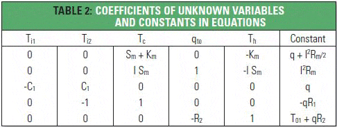
The coefficients of the unknown variables and the corresponding constant terms for each equation may be grouped in a tabular form as shown in Table 2. So doing, the top row represents the column vector of unknowns, the columns beneath each unknown variable make up the coefficient matrix and the rightmost column the constant vector.
The coefficient matrix below comprises the known coefficients of the unknown variables of the equations, as shown in Table 2,
the column vector of unknown variables which we seek to solve is,
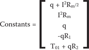
and the column vector comprising the known constants on the right hand side of each equation is,
A matrix equation such as (11) may be solved for the unknown variables by multiplying the constant vector by the inverse of the coefficient matrix,
Many computational aids such as MathCad [5], Matlab [7], and EXCEL [8] can be used to obtain the matrix inverse of the coefficient matrix and multiply by the constant vector to obtain the desired solution vector.
To demonstrate the potential enhancement with thermoelectrically augmented cooling, we now turn our attention to some numerical results obtained using the method described above. For purposes of illustration, a small enclosure with an allowable opening in one side of 100 mm x 100 mm is assumed. It is further assumed that the base dimensions of the internal and external air-cooling heat sinks are 100 mm x 100 mm. Before proceeding further it is necessary to assign values to the thermoelectric module cooling parameters, Sm, Km,and Rm. The same 40 mm x 40 mm TE module considered by the author in an earlier article [9] will be considered here. In the earlier article, the author illustrated the calculation of single module TE parameters from vendor data, using the method discussed by Luo [4]. The values for the example TE module were found to be:
Sm = 0.068 V/K
Km = 0.712 W/K
Rm = 2.307 Ω
However, to increase the overall heat pumping capacity, four of these TE modules can be sandwiched in a 2 x 2 array between the bases of the internal an external heat sink. Consequently, the parameters for the array of TE modules will simply be four times the value for a single TE module or,
Sm = 0.272 V/K
Km = 2.848 W/K
Rm = 9.228 Ω
Also, if we assume that the TE modules are wired in series, the current, I, through each module will be the same and equal to the total current.
Calculations were performed for a range of heat sink resistances to show the effects of this parameter, coupled with the thermoelectric cooling effects. The heat sink thermal resistances used in the calculations were 0.075, 0.125 and 0.175 oC/W and were considered to have the same value for the heat sink within and outside the box (i.e. R1 = R2). The internal air flow rate within the box was assumed to be 20 CFM (0.00944 m3/s).
As noted earlier, equations (6) and (7) are in Kelvin temperature units. Therefore, the temperature of the outside cooling air, T01, used in the calculations, must also be in degrees Kelvin and the temperatures obtained from equation (12) will be in degrees Kelvin. However, for ease of understanding, the temperatures reported in the following figures have been converted to degrees Centigrade.
Figure 2 illustrates both the effect of increasing electric current through the TE modules and heat sink thermal resistance, with a heat load of 100 watts from the electronics and an outside air temperature of 35 oC. The solid lines represent the cooling air temperature, Ti1, within the box with the TE modules sandwiched between the heat sinks and the dashed lines represent the temperatures obtained without the TE modules. As can be seen, at low values of electric current, the presence of the TE modules result in higher cooling air temperatures within the box. This is because at low electric current, the Peltier heat pumping effect is offset by the thermal resistance across the TE modules. As current is increased the Peltier heat pumping effect becomes more significant and the inside cooling air temperature can be decreased significantly. However, as electric current continues to be increased, the Joule heating (i.e. heat dissipation) within the TE modules becomes increasingly significant causing the inside cooling air temperature to bottom out and then begin to rise if current is increased still further.
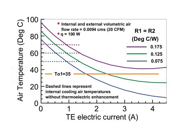
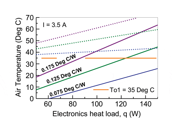
Figure 3 illustrates the effect of the electronics heat dissipation on cooling air temperature within the box, with a constant current of 3.5 amperes through the array of TE modules and an outdoor temperature of 35 oC. The internal and external air flow rate was held constant at 0.0094 cms (20 CFM). As can be seen, for the heat load range considered for this analysis, the cooling air temperatures obtained in all the cases are lower than could be achieved without employing TE enhancement. It should also be noted that, depending on heat load and heat sink thermal resistance, in many cases the cooling air temperature is even lower than could be obtained using outside air for cooling.
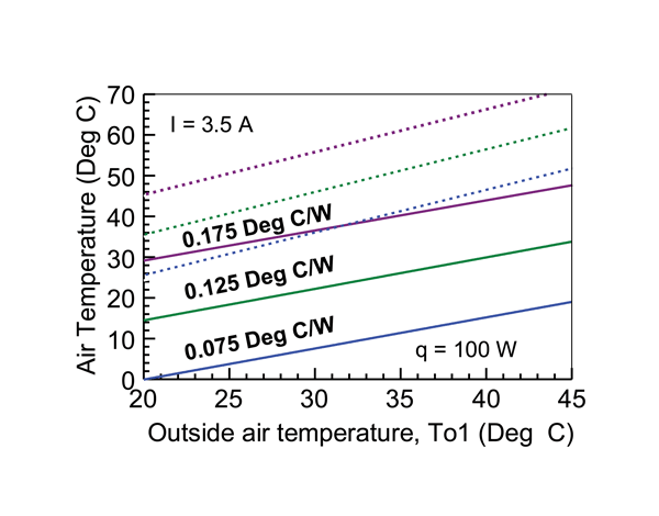
The results in Figure 4, show the effect on cooling air temperature within the box, of supplying a fixed current of 3.5 amperes to the TE modules and for a fixed electronics heat load of 100 watts. It can be seen that in this case, the resulting cooling air temperatures are always below the cooling air temperatures that could be achieved without thermoelectric enhancement.
The equations and solution methodology presented in this article can provide a useful tool with which to obtain a preliminary estimate of the effectiveness of thermoelectric augmentation in providing cooling to electronic components in a closed box.
Of course, when considering the use of thermoelectrics for cooling applications, the designer should be cognizant of the electrical power required to drive the thermoelectric elements, which is given by equation (7). The cooling efficiency of thermoelectric devices relative to their power consumption, as with other types of heat pumping devices, may be characterized in terms of Coefficient of Performance (COP). COP, is defined as the ratio of cooling (q) provided over the electrical energy consumed (qte) to produce the cooling effect. For example, for the results shown in Figure 3, the COPs ranged from 0.3 to 0.4 at heat loads of 50 or 60 W to around 1 at a heat load of 150 W. The range of heat sink thermal resistance values had only a little effect on the COP realized. Similarly, considering the results shown in Figure 4, COPs ranged from 0.6 to 0.7 with little effect due to heat sink thermal resistance or outside air temperature. As one might expect from equation (7) the principal effect on COP is caused by the electrical current required to drive the thermoelectrics. This is amply demonstrated considering the results presented in Figure 2. At electric currents around 1.25 A, the COPs calculated ranged from 6 to 6.4 depending on the value of heat sink thermal resistance. Although these COPs may seem good, in this case the cooling air temperature within the box is no lower than could be achieved without thermoelectrics. As current is increased in Figure 2, the COP realized decreases rapidly to about 0.65 at a current of 3.5 A. However, even though the COP has dropped, this coincides with the maximum reduction of air temperature within the box by as much as 20 to 30 Centigrade degrees below those achieved without thermoelectric augmentation. For comparison, the COP values realized by conventional vapor compression refrigeration systems may typically vary from 1 to 4.
Finally, it should be noted that a number of vendors provide thermoelectric heat exchangers for cooling air within in a closed box. The interested reader may find a number of vendor products and examples by conducting an internet web search using the terms “thermoelectric air cooler” or “thermoelectric air conditioner.
References
1. Simons, R.E., “Estimating Temperatures in an Air-Cooled Closed Box Electronics Enclosure,” ElectronicsCooling, February 2005.
2. Godfrey, S., “An Introduction to Thermoelectric Coolers” ElectronicsCooling, September 1996.
3. Simons, R.E., “Application of Thermoelectric Coolers for Module Cooling Enhancement,” ElectronicsCooling, May 2000.
4. Luo, Z., “A Simple Method to Estimate the Physical Characteristics of a Thermoelectric Cooler from Vendor Datasheets,” Electronics Cooling, August 2008.
5. http://en.wikipedia.org/wiki/Mathcad .
6. Simons, R.E., “Using a Matrix Inverse Method to Solve a Thermal Resistance Network,” Electronics Cooling, May 2009.
7. http://www.mathworks.com/products/matlab/ .
8. http://www.ehow.com/how_5898417solve-equations-matrix-method-excel.html .
9. Simons, R.E., “Using Vendor Data to Estimate Thermoelectric Module Cooling Performance in an Application Environment,” ElectronicsCooling, July 2010.

