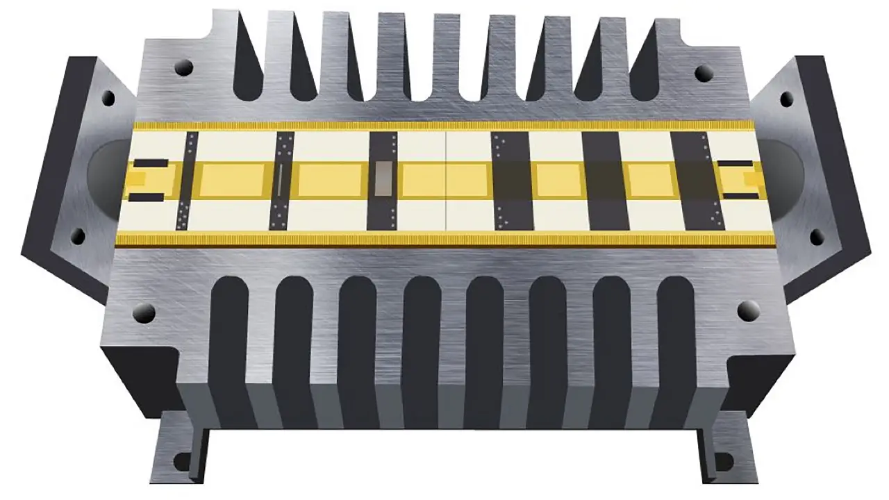
The testing and troubleshooting of high power and high frequency systems such as distributed antenna systems (DAS), base stations, and various radar applications require buffering to prevent a power overload to the testing equipment and sensitive subsystem internal circuitry. With powers as high as 60 dBm (1000 Watts), radio frequency (RF) terminations and attenuators are relied upon to dissipate much of this microwave energy. A number of factors must be taken into account in the design of these high power handling components, including designing the internal resistive network with minimal reflections and a low Voltage Standing Wave Ratio (VSWR), which is a measure of power reflected back at the source, even at high temperatures as well as minimizing the thermal resistance of the device.
WHAT IS A TERMINATION/LOAD?
Terminations are one-port devices meant to absorb microwave energy by dissipating it as heat. This has to be accomplished with little reflections; in other words, the termination must be impedance matched (often 50 ohms) to the device under test (DUT). High powered coaxial terminations leverage heat sinks to dissipate heat while the 50 ohm impedance is often generated with precision thin film resistors. Loads can be used to test the frequency response of a multi-port component, such as a 3-port switch, where one (or more) ports can be terminated in order to properly measure the transmission of a signal in the two active ports. When testing a T/R (transmit/receive) module, high power terminations are often used as “dummy loads” in place of an antenna to protect the sensitive internal circuitry of the equipment that would be damaged by the power reflections resulting from a temporary open-circuit.
WHAT IS A FIXED RF ATTENUATOR?
Whether being used for microwave power measurements or to minimize reflections in a RF signal chain, attenuators are immensely valuable for protecting sensitive equipment. Attenuators are 2-port components that essentially reduce the amplitude of a signal traveling from the input to the output of the device by means of an internal resistive network or transistor-based network. These high utility components can come in many forms based on the application. For instance, transistor-based programmable attenuators can be used to control the gain of a system while fixed attenuators are more often used as ‘padding’, or protection.
To dissipate power on the order of 100W or more, such as in radar systems, fixed RF attenuators have a large advantage over the other constructions (Figure 1). Significant losses occur in the switches of programmable attenuators causing deviations in the attenuation flatness over frequency. In high power scenarios, the parasitic capacitance from the high-power internal resistors and ground plane as well as the reactance of PIN diodes in programmable and continuously variable attenuators lead to these deviations. While methods to mitigate these sources of error do exist, they are generally impractical due to enormously more complex and expensive system thermal management requirements.

HOW RF ATTENUATORS AND TERMINATIONS DISSIPATE HEAT
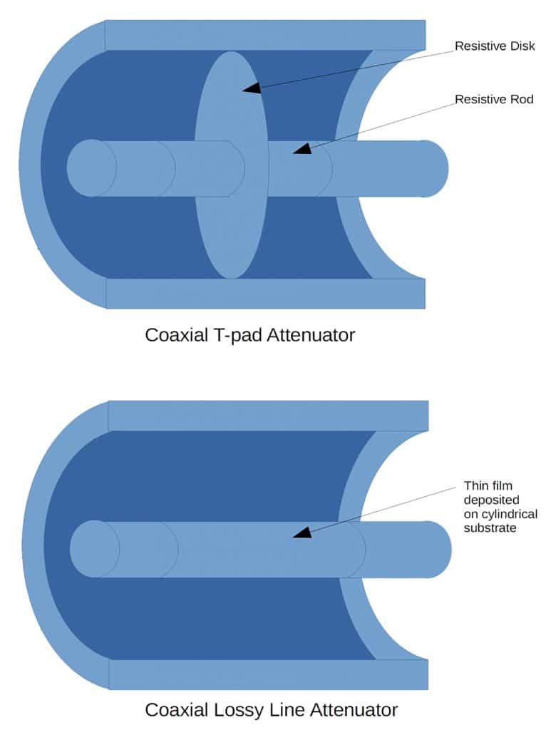
The design of fixed coaxial attenuators has evolved significantly since the T-pad and Pi-pad attenuator with distributed internal resistive disks and rods and the lossy in-line style attenuator where the center conductor consisted on a cylindrical element with resistive film deposited on the surface Figure 2. These constructions were effectively replaced by the ‘card’ coaxial attenuator design by Weinschel, in which the inner resistive element became what is essentially a thin film resistor–this greatly increased the bandwidth of the device [1]. Replacing the barrelshaped outer conductor with a heat sink increased the power handling capability beyond 10 W as the larger surface area could better dissipate heat to the environment through radiation. This design for a high powered attenuator has been widely adopted for fixed RF coaxial attenuator designs due to its simple approach for thermal management.
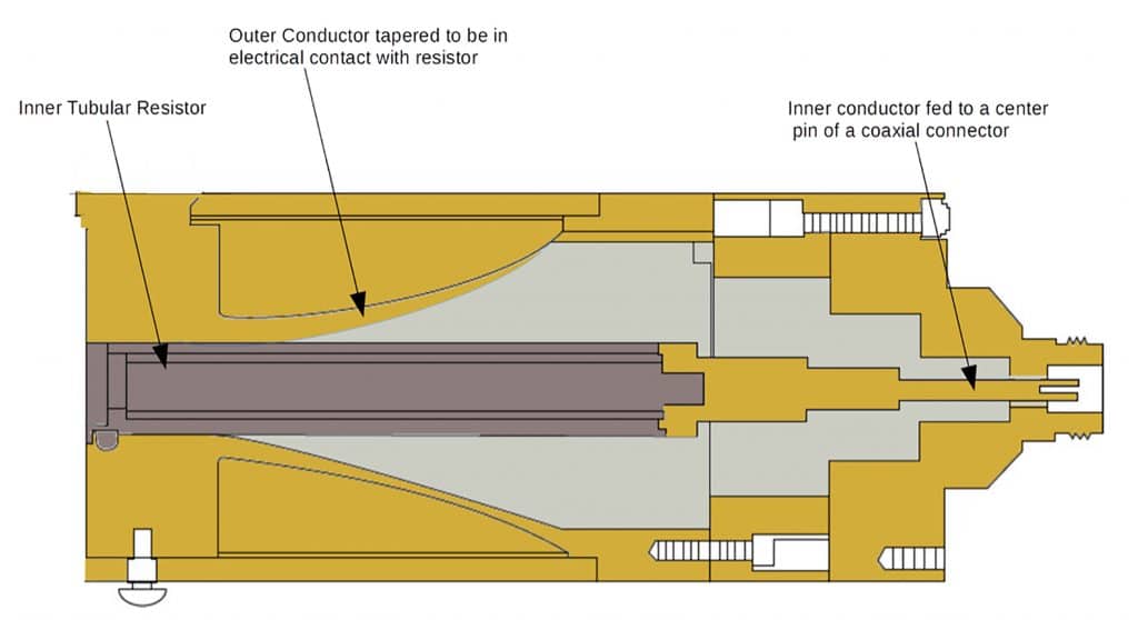
Similar to attenuators, early design methodologies for coaxial terminations included an inner conductor comprised of a tubular film resistor that often included a ceramic tube with resistance film coated on the outer surface while the surrounding metallic outer conductor was tapered at one end to electrically connect with the resistor (Figure 3). Current termination designs are similar to attenuators with internal precision resistor networks and an external heat sink and outer conductor.
CENTRAL RESISTIVE ELEMENT
While prior designs for the central attenuating element included tubular resistors or a Pi- or T-pad attenuator topologies (Figure 4a/4b), more recent constructions employ a distributed thin film topology in which precision laser trimmed resistors sit on a dielectric substrate to accomplish the internal resistive topology as shown in Figure 4c where the characteristic impedance is given in Equation 1.
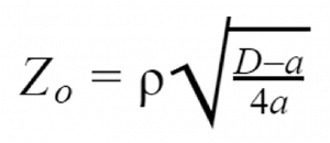
Where Zo is the characteristic impedance, ρ is the resistivity of the thin film, D is the distance between the ground electrodes, and a is the thickness of the center electrode.
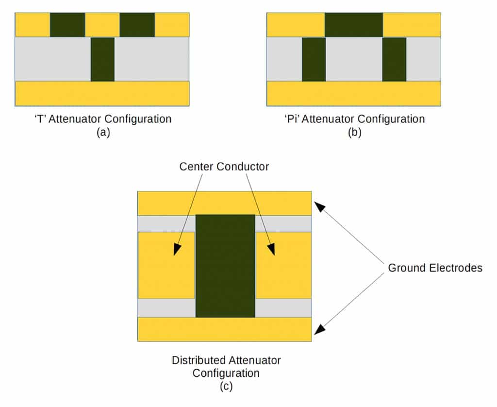
RF Attenuators and terminations have evolved in design with thin film technology and resistive materials such as Nichrome, Tantalum Nitride, and Silicon Chrome, as drastically higher frequencies can be achieved with extremely high tolerance resistances. The sheet resistance is dependent on the thickness of the resistive film, its resistivity, and its dimensions (length and width). Since the resistivity of the material is a constant and there is a reliably homogenous layer of film across all resistors, the real variables are essentially the length and width. Additionally, the temperature coefficient of resistance (TCR) values of the thin films can now be manufactured with values of less than 10 ppm/ºC absolute [2], which is significantly better than discrete resistor counterparts. Ceramics are often the substrate of choice as materials such as Aluminum Nitride, Beryllium Oxide, and 99% Alumina exhibit a low coefficient of thermal expansion (CTE) and high thermal conductivity. Materials with a high CTE are likely to change in impedance where a small impedance change from 50 ohms can cause significant reflections at high powers, choosing resistive and dielectric materials with a similar CTE can mitigate this effect.
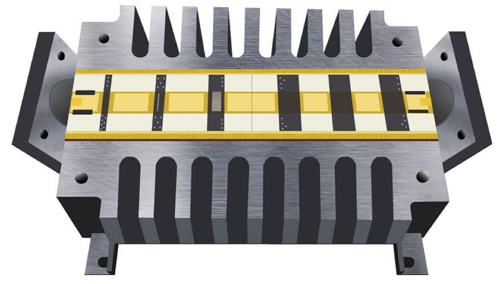
The ceramic insulating substrate often sits on milled grooves directly in the heat sink, or outer conductor, forming a connection between the ground electrodes on the substrate and outer conductor ground path as well as a conductive path for heat dissipation. Further cooling can be accomplished by joining the ground planes with solder, or by integrating bonded fins (Figure 5) with the ceramic’s ground to enhance convection and reduce the thermal resistance. The dimensions of the resistors and respective contacts/flanges increase in order to better conduct thermal energy generated from joule heating whereby the energy is channeled through the heat sink. The interconnections in the central attenuating element are typically gold-plated. While metals such as copper or silver offer higher thermal conductivity gold’s low contact resistance and imperviousness to corrosion/oxidation make it a better plating surface for high frequency systems. Since gold is also a malleable metal, it requires significantly less pressure to form the functional internal spring loaded contacts often form the electrical connection between the substrate and the RF connectors.
HEAT DISSIPATIVE OUTER CONDUCTOR
Often made of black anodized aluminum, the fixed attenuator and termination outer conductor is composed of various extruded heatsink topologies. The black coating increases the surface emissivity so that the conductor can more readily radiate the heat from the internal resistive elements; this only slightly improves the thermal management since most of the radiated heat radiated falls on adjacent fins [3]. A commercially extruded aluminum surface typically has emissivity in the range of 0.09; anodization increases the emissivity to 0.77-0.85 [4]. Additionally, the thin oxidized layer of anodization metal’s microscopic pores inhibit corrosion of the component.
Generally, the maximum temperature ratings of high power RF attenuators and terminations are on the order of 125oC while the length, width, and height can range from 10 to 20 inches (25 to 50 cm). Due to these constraints radiation alone is insufficient to cool fixed RF attenuators and terminations by more than a few degrees [5].
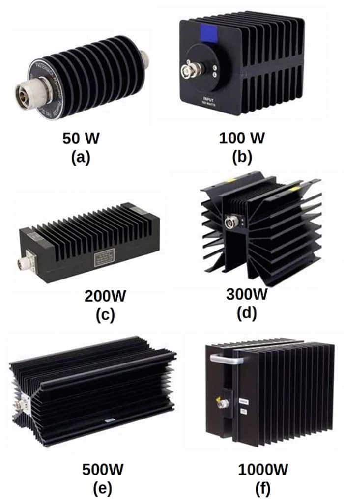
The main source of cooling for these components come from the combination of the conduction, through contact between the PCB and the heatsink, and natural convection cooling from the external conductor’s fins. Nevertheless, the heatsink topologies of attenuators come in a plethora of shapes and sizes. Figure 6 introduces a number of fixed attenuator topologies with high power capacities ranging from 50W to 1000W. For up to 50W of continuous wave (CW) power, the annular (radial) fin topology (Figure 6a) is generally used. Since the convective thermal resistance of these fins depends on the fin diameter and fin spacing, lower power rated attenuators and terminations have significantly smaller diameters than those with 50W or more. It should be noted that there are also broadband, high-powered fixed attenuators with radial fin configurations that have a long length. The dimensionally smaller resistors have better highfrequency performance and-the resistive stages are cascaded to achieve a particular insertion loss requirement. Dimensionally larger resistors generally have better power handling; since their increased surface area and larger geometries better spread the dissipated power across the device.
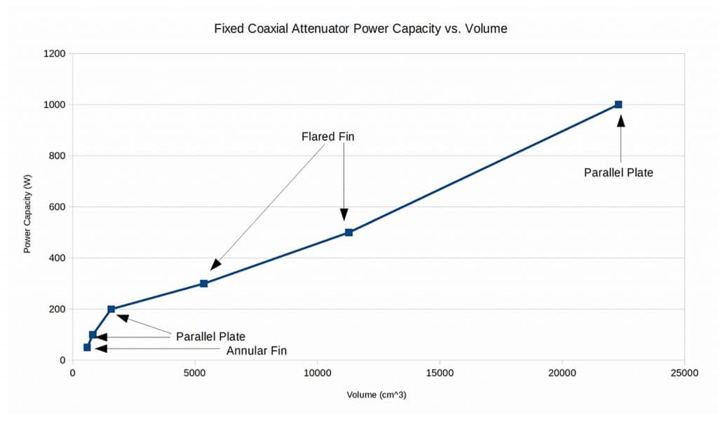
The commonly used straight fin heat sink (Figure 6c) operates with the power dissipating central component located at the center of the structure. The central component can either be placed on a solid aluminum baseplate (Figure 6c) or another identical parallel plate heat sink structure (Figure 6b). As shown in Figure 6d and Figure 6e, flared fins can be leveraged for higher powered components as they can improve heat transfer by at least 20% better than the straight fin topology, even with approach velocities as low as 1 m/s. This improvement can be particularly beneficial when relying on natural convection [6]. Figure 6f shows another larger parallel plate topology with a gap between the extruded heat sinks for improved airflow. Figure 7 further illuminates the relationship between size and power handling, where the various heat sink topologies shown in Figure 6 are labeled for clarity.
CONNECTOR CONSIDERATIONS
Since the main purpose of the connectors in a coaxial RF attenuators and terminations are to channel the microwave energy, the choice and design of the connector depends heavily upon the maximum frequency for the given application as that decides the maximum allowable diameter for the outer conductor. Naturally, there is a tradeoff since the larger diameter increases the maximum input power but limits frequency while the smaller diameter increases the maximum frequency but limits the input power. For this reason, connector heads such as 7/16 DIN and N-type are rated for much higher power than SMA, or TNC connectors.
CONCLUSION
RF attenuators and terminations must ultimately strike a balance between maximum frequency and power handling. Once the internal dimensions of the resistive network have been devised there are a number of other factors to maximize heat dissipation including:
- Choosing insulating and resistive materials with a similarly low CTE and a high thermal conductivity.
- Designing a distributed resistive topology in order to better spread heat.
- Optimizing the heat flow from the substrate to the mounting base by means of fins on ground planes, soldered connections, milled grooves, silver-plating, etc.
- Choosing heat sink topology for optimal thermal dissipation (flared fins, plate fins, black, anodized, etc).
Fixed RF attenuators are one of many attenuator topologies, but offer the best thermal management. High powered RF terminations are similarly designed to attenuators as they are both passive devices meant to absorb and dissipate RF energy.
REFERENCES:
[1] https://www.google.com/patents/US3157846
[2] https://www.vishay.com/docs/49562/49562.pdf
[3] Electronics Product Design By V.S.Bagad
[4] http://www.engineeringtoolbox.com/emissivitycoefficients-d_447.html
[5] http://www.heatsinkcalculator.com/blog/the-importance-ofradiation-in-heat-sink-design/
[6] Forghan, F., Goldthwaite, D., Ulinski, M., Metghalchi, M., 2001, Experimental and Theoretical Investigation of Thermal Performance of Heat Sinks, ISME May.
