by: Pritish R. Parida, Mark Schultz & Timothy Chainer
J. Watson Research Center, Yorktown Heights NY, USA
INTRODUCTION
In the Moore’s Law race to keep improving computer performance, the IT industry has turned upward, stacking chips like nano-sized 3D skyscrapers. But those stacks, like the law they’re challenging, have their limits, due to overheating. A solution to this problem is embedded cooling in which a coolant is made to flow between the stacked high power active layers.
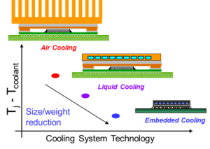
Today, most chips are cooled by fans which push air through heat sinks that sit on top of the packaged chips to carry away excess heat. Advanced water cooling approaches, that are more effective than air-cooling approaches, replace the heat sink with a cold plate that provides more efficient heat transfer. However, because of its electrical conductivity, moving water into a chip stack requires complex isolation measures to protect the chip, and requires impractically large channels to cool large high-power die at reasonable pressure drops. The new chip-embedded cooling approach, described in this article, utilizes a benign nonconductive fluid to take this next step of bringing the fluid into the chip (as shown in Figure 1 below). This does away with the need for a barrier between the chip electrical signals and the fluid. It not only delivers a lower device junction temperature (Tj), but also reduces system size, weight, and power consumption (SWaP).
Figure 1. Different types of cooling solution.
This technology provides a solution to cooling 3D chip stacks where a heat sink or cold plate is inadequate for 3D stacking of high power chips because of their inability to cool chips in the middle and bottom of the stack. This chip-embedded cooling technology circumvents that problem by pumping a heat-extracting dielectric fluid (like the one used in refrigeration systems) into microscopic gaps, some no wider than a single strand of hair (~100 μm), between the chips at any level of the stack. The dielectric fluid used can come into contact with electrical connections, so is not limited to one part of a chip or stack. This ability benefits chip stacks in terms of materials and architecture, such as putting memory and accelerator chips on top of high power chips in the stack, which can improve the speed of everything from graphics rendering to deep learning algorithms [1, 2].
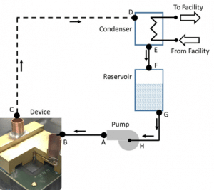
The coolant is pumped into the chips, where it removes the heat from the chip by boiling from liquid-phase to vapor-phase. It then re-condenses, dumping the heat to the ambient environment where the process begins again, as shown in Figure 2. As this cooling system doesn’t need a compressor, it can operate at much lower power compared to typical refrigeration systems. Key elements of the approach and results are presented in this article, with additional details available in references [1-10].
RADIALLY EXPANDING MICRO-CHANNELS WITH MICRO-PIN FINS
Two-phase flow boiling has long been proposed as a potential method for cooling high performance computer systems [11, 12]. A large body of work investigating and developing technologies appropriate for cooling electronics with two phase flow boiling in parallel micro/mini-channels exists [13], but parallel channel two-phase flow is challenged by instability issues, particularly with non-uniform power maps. We utilize a significantly different approach to embedded cooling [3,4]. Rather than moving coolant from one edge of the die to the other through long parallel channels, a dielectric coolant (R1234ze or similar) is fed in at the center of the die, moves through radially expanding channels, and exits at the edges of the die. This approach provides better energy effciency and maximum critical heat flux with the resulting reduced flow path [4].
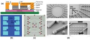
The cooling capability was demonstrated on a specially constructed thermal test vehicle (see Figure 3) designed to mimic the heat generation capability of real microprocessors without requiring actual transistor-based circuitry [3, 10]. In these studies, power densities of 350 W/cm2 within an area measuring 3.6 mm x 4.8 mm representing a microprocessor core and 200 μm x 200 μm hot-spot power levels of more than 2 kW/cm2 were shown to be effectively cooled.
Figure 3. (a) Packaged thermal test vehicle. (b) Representative power map. (c) Relative thermal sensor locations. (d) SEM image of orifices and radial expanding channels.
EMBEDDED TWO-PHASE LIQUID COOLED MICROPROCESSOR (ECM) MODULE
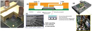
To demonstrate radial embedded two-phase cooling in real devices a commercial two-socket, 2U form factor server was used. The server’s 8-core microprocessor modules were modified into embedded two-phase liquid cooled microprocessor (ECM) modules. Modification of these modules into ECM modules (Figure 4) required the creation of an embedded channel design followed by the development of a module fabrication and assembly process. Overall, the embedded cooling structures, including micro-pin field, coolant flow directing walls and orifices, were designed with constraints compatible with future 3D structures, which would include through silicon vias (TSVs). To modify the microprocessor module for embedded cooling the lid, seal and thermal interface material were removed to expose the processor die. A deep reactive ion etch (DRIE) of the processor die was performed to generate the 120 µm deep cooling channels structures (Figure 4(c)) on the backside of the processor die. Next, a glass die was bonded to the etched processor die to create the top wall of the micro-channels. Finally, a brass manifold lid, which provides for coolant supply and return, was bonded to the glass manifold die and the organic substrate using an adhesive. The ECM module was placed in a commercial server, as shown in Figure 4(d). Additional detail on the ECM module design and fabrication process can be found in Schultz et al. [8, 9].
The coolant (R1234ze) enters the ECM module and passes through 24 inlet orifices to distribute the flow among the corresponding 24 radial expanding channels (6 per quadrant). A combination of detailed full-physics [14] and reduced-physics models [15] was used to model the two-phase flow and heat transfer process to design and optimize the cooling channels structures including the central inlet diameter, dimensions of inlet orifices and number of radial expanding channels. The coolant removes heat from the chip as it flows through the radial expanding channels and transitions from liquid phase to vapor phase before exiting the ECM module as a liquid-vapor mixture. The coolant delivery to and return from the ECM module is controlled by the test system shown in Figure 2. The condenser connected downstream of the ECM module, extracts the heat from the exiting liquid-vapor mixture and condenses the vapor back to liquid. The liquid coolant then flows into the reservoir and is pumped back to the ECM module.
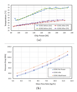
It is of interest to compare the performance of ECM modules with their baseline air-cooled state. Shown in Figure 5(a) is the before (air-cooled) and after (two-phase liquid cooled) comparison of average cores temperature for two ECM modules. The cores temperature was measured using 40 (5 per core) on-chip digital thermal sensors [9]. Coolant inlet temperature in both cases is 25 ºC. The dielectric coolant mass flow rate is 9 kg/hr at a pressure drop of 75 kPa (~11 psi) which, for a pump efficiency of 0.1 results in ~1.5 W of coolant pumping power. The improvement in operating temperature is substantial. Note that the air-cooled curve levels off at around 70 ºC as the system fans speed up (~65%) to prevent overheating [1]. At the highest power operation (4.3 GHz) the reduced operating temperature results in over a 10 watt decrease in the power consumed by the microprocessor along with a significant reduction in fan power (15+W) that would be concomitant with such a system [9].
Shown in Figure 5(b) is pressure drop versus flow rate data for an ECM module at three power levels. While there is an observable increase in pressure drop at full power, it is still relatively small. Therefore a coolant supply system utilizing a relatively simple “pump-on” operating mode, without flow or pressure control, would have relatively minor changes in flow and/or pressure drop with changes in operational power level. This also implies that modules could conceivably be operated in parallel without active flow balancing between modules when module power levels change. In all cases, the observed pressure drop was quite stable, with no evidence of flow instability.
Figure 4. (a) Cut-away view and (b) cross-sectional view of the ECM module. (c) SEM image of cooling channel structures. (d) ECM installed in a commercial server.
THERMAL MODELING AND VALIDATION
The development of an embedded two-phase cooling solution requires a comprehensive understanding to design the various constituent sub-components such as inlet orifices, two-phase flow in micro-channels, two-phase flow through micro-pin-fin arrays oriented at arbitrary angles relative to the flow direction, etc. A key challenge is to develop high fidelity conjugate thermal models of the chip-package having spatially varying, and workload-, temperature-, and operating frequency-dependent heat sources together with a two-phase microfluidic convection network. This includes integrating together the variations in coolant saturation temperature, local heat transfer rates, friction coefficients, and vapor quality along with complex thermal conduction in the microprocessor package.
We have developed a novel Hybrid Thermal Model (HTM) that uses characteristic features of both reduced-physics and full-physics models, and integrated that with an electrical model of the microprocessor for fast and accurate prediction of thermal behavior of an embedded two-phase liquid cooled high power electronic devices. A comparison of the junction temperature prediction by the HTM against the on-chip digital thermal sensor data for an ECM module demonstrates the model accuracy (see Figure 6). Further details have been published [5, 6].
Figure 6. Comparison of chip temperature prediction by HTM against the on-chip digital thermal sensor data for an ECM module.
CONCLUSION
Advanced thermal solutions provide three major benefits to computer efficiency. First, integration of liquid cooling into the chip reduces chip junction temperature and leakage power, which lowers the energy per computation. Embedded two-phase cooling of microprocessor modules demonstrated junction temperature reduction by 25 ºC, and chip power usage reduction by 7 percent compared to traditional air cooling. Second, chip-embedded cooling reduces the thermal resistance between the chip and the coolant allowing coolant temperatures above the outdoor ambient temperature, thus eliminating sub-ambient energy intensive cooling requirements. Finally, the integration of chip stack embedded liquid cooling provides a path to high bandwidth 3D chip stacking of heterogeneous components, which has the potential for computational performance improvements.
ACKNOWLEDGEMENT
This project was supported in part by the U.S. Defense Advanced Research Projects Agency Microsystems Technology Office ICECool Fundamentals Program under award number HR0011-13-C-0035 and ICECool Applications Program under the award number FA8650-14-C-7466. Disclaimer: The views, opinions, and/or findings contained in this article are those of the author(s) and should not be interpreted as representing the official views or policies of the Department of Defense or the U.S. Government. Distribution Statement “A” (Approved for Public Release, Distribution Unlimited).
The authors would like to acknowledge the contributions of IBM Research colleagues Pradip Bose, Thomas Brunschwiler, Alper Buyuktosunoglu, Evan Colgan, Bing Dang, Ute Drechsler, Michael Gaynes, John Knickerbocker, Yang Liu, Gerard McVicker, Chin Lee-Ong, Stephan Paredes, Arvind Sridhar, Cornelia Tsang, Augusto Vega and Fanghao Yang.
AUTHORS


REFERENCES
[1] T. J. Chainer, M. D. Schultz, P. R. Parida, M. A. Gaynes, “Improving Data Center Energy Efficiency with Advanced Thermal Management”, IEEE Transactions on Components, Packaging and Manufacturing Technology, vol.7, issue 8, pp. 1228 – 1239, 2017.
[2] Parida, P. R., A. Vega, A. Buyuktosunoglu, P. Bose, T. Chainer, “Embedded Two-Phase Liquid Cooling for Increasing Computational Efficiency”, Proceedings of 15th IEEE ITherm Conference 2016, Las Vegas, NV, May 31-June 3 2016.
[3] Schultz, M., Yang, F., Colgan, E., Polastre, R., Dang, B., Tsang, C., Gaynes, M., Parida, P. R., Knickerbocker, J. and Chainer, T., “Embedded Two-Phase Cooling of Large 3D Compatible Chips with Radial Channels”, Journal of Electronic Packaging, vol. 138(2), 2016.
[4] C. L. Ong, S. Paredes, A. Sridhar, B. Michel, and T. Brunschwiler. “Radial hierarchical microfluidic evaporative cooling for 3-d integrated microprocessors.” 4th European Conference on Microfluidics, Limerick, Ireland, 2014.
[5] Parida, P. R., Sridhar, A., Vega, A., Schultz, M., Gaynes, M., Ozsun, O., McVicker, G., Brunschwiler, T., Buyuktosunoglu, A., Chainer, T., “Thermal Model for Embedded Two-Phase Liquid Cooled Microprocessor”, Proceedings of 16th IEEE ITherm Conference 2017, Orlando, FL, May 30 – June 2, 2017.
[6] Parida, P. R., Sridhar, A., Schultz, M., Yang, F., Gaynes, M., Colgan, E., Dang, B., McVicker, G., Brunschwiler, T., Knickerbocker, J., Chainer, T., “Modeling Embedded Two-Phase Liquid Cooled High Power 3D Compatible Electronic Devices”, Proceedings of 33rd IEEE Semi-Therm Symposium 2017, San Jose, CA, March 13-17, 2017.
[7] Dang, B., Colgan, E., Yang, F., Schultz, M., Liu, Y., Chen, Q., Nah, J. W., Polastre, R., Gaynes., M., McVicker, G., Parida, P., Tsang, C., Knickerbocker, J. and Chainer, T., “Integration and Packaging of Embedded Radial Micro-channels for 3D Chip Cooling”, Proceedings of IEEE ECTC Conference 2016, Las Vegas, NV, May 31-June 3 2016.
[8] Schultz, M., Parida, P. R., Gaynes, M., Ozsun, O., McVicker, G., Drechsler, U., Chainer, T., “Microfluidic Two-Phase Cooling of a High Power Microprocessor Part A: Design and Fabrication”, Proceedings of 16th IEEE ITherm Conference 2017, Orlando, FL, May 30 – June 2, 2017.
[9] Schultz, M., Parida, P. R., Gaynes, M., Ozsun, O., Vega, A., Drechsler, U., Chainer, T., “Microfluidic Two-Phase Cooling of a High Power Microprocessor Part B: Test and Characterization”, Proceedings of 16th IEEE ITherm Conference 2017, Orlando, FL, May 30 – June 2, 2017.
[10] Yang, F., Schultz, M., Parida, P., Colgan, E., Polastre, R., Dang, B., Tsang, C., Gaynes, M., Knickerbocker, J., Chainer, T., “Local Measurements of Flow Boiling Heat Transfer on Hot Spots in 3D Compatible Radial Microchannels”, Proceedings of ASME InterPACK / ICNMM Conference 2015, San Francisco, CA, July 6-9, 2015.
[11] Kandlikar, S. G., 2012, “History, Advances, and Challenges in Liquid Flow and Flow Boiling Heat Transfer in Microchannels: A Critical Review,” J. Heat Transf.-Trans. ASME, 134(3).
[12] Thome, J. R., 2004, “Boiling in microchannels: a review of experiment and theory,” International Journal of Heat and Fluid Flow, 25(2), pp. 128-139.
[13] Bhavnani, S., Narayanan, V., Qu, W. L., Jensen, M., Kandlikar, S., Kim, J., and Thome, J., 2014, “Boiling Augmentation with Micro/Nanostructured Surfaces: Current Status and Research Outlook.” Nanoscale Microscale Thermophys. Eng., 18(3), pp. 197-222.
[14] Parida, P. R. and Chainer, T., “Eulerian Multiphase Conjugate Model Development and Validation for Flow Boiling in Micro-Pin Field”, Proceedings of 15th IEEE ITherm Conference 2016, Las Vegas, NV, May 31-June 3 2016.
[15] Parida, P. R., “Reduced Order Modeling for Chip-Embedded Microchannel Flow Boiling”, Proceedings of ASME InterPACK / ICNMM Conference 2015, San Francisco, CA, July 6-9, 2015.
