ABSTRACT
Testing standards provide a common framework for collecting and reporting data. Without a clearly defined testing standard, it is impossible to compare experimental data measured by different labs since differing test conditions may mask the very effect being tested. For this reason, a Thetajc standard is needed to specify testing conditions that allow for an equitable comparison of data, such as to determine which assembly process or package style has a lower thermal resistance. This study presents a summary of test data collected for three different thermal test vehicles having Thetajc values of approximately 7°C/W, 2.5°C/W, 1.8°C/W and 0.07°C/W. Recommendations are provided on two different methods for measuring the case temperature depending on the Thetajc value in question. For Thetajc values less than a critical value, embedded case thermocouples should be attached to the case. Otherwise the thermocouple may be flush mounted to the surface of the heat sink.
INTRODUCTION
There are strong opinions on the relative merits for performing steady-state Thetajc tests. Lasance and Lacase [1] raised concerns on the time required to perform steady-state measurements. Also, they indicated steady-state tests are difficult to perform if high accuracy measurements are required. Others have indicated a reluctance to adopt a new test method since there is an historical precedent for continuing to use existing methods. There are many challenges that must be addressed including; the effects of power map, differences in heat sink design, differences in thermal interface material between case and heat sink (commonly referred to as TIM II), differences in sensing junction and case temperature and quantifying the dissipative power. Over the past 15 years, the JEDEC thermal standards committee, JC15, has worked on establishing a steady-state Thetajc standard but has not made significant progress due to many of these challenges. Although progress on the steady-state Thetajc standard has languished over the years, the transient standard JESD 51-14 [2] was released and now is available. This standard was widely accepted for smaller packages that have a single heat transfer path. However, for larger packages, such as a flip chip ball grid array (FCBGA) package, two heat flow directions are present (between the active
side of the die and the case and between the die and substrate). Presently, transient testing cannot experimentally quantify the power distribution between the top of the package and through the board. Therefore, the transient method cannot be applied to large packages with two directions of heat flow. Steady-state testing also provides a more realistic testing condition because it allows the test package to reach a temperature profile similar to the functional package operating at its desired power level. As a result, factors controlling Thetajc, such as the temperature-dependent material properties and package warpage, will more closely represent those found in a functional package.
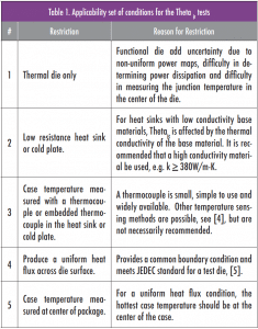
Various methods for measuring the case temperature are outlined in Galloway and Okpe [3], however; based on the experience of the authors, the thermocouple is a better choice for measuring case temperature. Thetajc measurement uncertainties attributed to instrumentation are discussed in De Los Heros et al. [4]. Rather than address all the expressed concerns, the proposed standard restricts the set of conditions to those most easily controlled and more commonly employed when making Thetajc measurements. Table 1 summarizes the restricted set of conditions considered for the proposed Thetajc standard. It is understood that, in some cases, not all conditions will be satisfied. The tradeoff in making the standard less restrictive is that there may be greater variability in results when testing the same packages. The factors that guided the development of the Thetajc standard include; ensuring that the method is based on sound scientific principles, the data produced from the testing are useful and reproducible and that the equipment needed for the testing is readily available and not overly expensive.
TESTING OVERVIEW
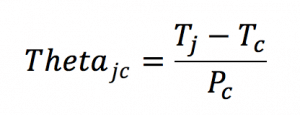
Thetajc is defined in equation (1) and includes the measurement of the junction temperature, Tj , case temperature, Tc , and power, Pc , leaving the case of the package.
(1)
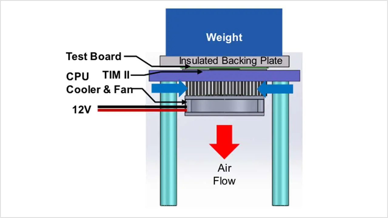
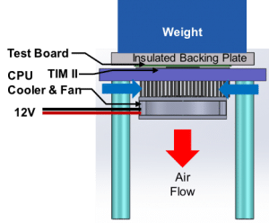
The power, Pc , required to evaluate Equation (1) will be lower than the supplied electrical power because it must not include the heat loss to the surroundings. An estimate of the heat loss should be provided using finite element analysis (FEA) or by other means. The heat loss, predicted using FEA, was 7% for a low-power package and 3% for two other high-power packages. An experimental method may be employed to approximate the heat loss by placing an insulating sheet of material (e.g. 2mm thick Teflon sheet) between the heat sink and the test vehicle. This allows a lower power setting to produce a similar junction temperature as measured during Thetajc tests. The amount of electrical power used to power the insulated package can be used as an approximation for the heat loss. Heat losses should be minimized by using proper insulating materials, see for example the insulating backing plate shown in Figure 1.
EXPERIMENTAL SYSTEM
The design and selection of the testing apparatus was made as simple as possible without taking away from the accuracy of the Thetajc test. A central processing unit (CPU) cooler was used as the cooling sink since it is widely available and is relatively inexpensive compared to a cold plate; however, it is more susceptible to ambient temperature variations. The CPU cooler has a case-to-ambient resistance of approximately 0.12C/W. It was fabricated using copper plate fins and a 7mm thick copper base. Figure 1 shows the test system including the CPU cooler, test board, insulated backing plate and a weight used to apply clamping pressure between the package and the heat sink.
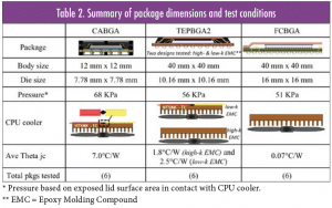
Three different test boards were selected including a carrier array ball grid array (CABGA) package, thermally enhanced plastic ball grid array (TEPBGA2) package and a flip chip ball grid array (FCBGA) package. A summary of the package information is included in Table 2. Two different CPU coolers were used based on the value of Thetajc. For high Thetajc values, a CPU cooler having an embedded thermocouple (TC) was used to measure the case temperature since the resistance of the thermal interface material between the case and CPU cooler (TIM II) was small in comparison to the value of Thetajc. This led to a slightly lower temperature measurement at the base of the CPU cooler than the package case. This simplifies testing since only one TC must be installed in the heat sink when testing multiple parts. Because the CABGA package has a relatively high Thetajc value, the embedded thermocouple CPU cooler was used. Similarly, the TEPBGA2 packages 3, 4, and 5, which were manufactured with low conductivity mold compound, used the embedded heat sink thermocouple to measure Thetajc. TEPBGA2 packages 1, 2 and 6 were manufactured using a high conductivity mold compound resulting in a lower Thetajc. The FCBGA package had an even lower Thetajc value. Both these package types required embedded case thermocouples to accurately measure Thetajc and did not use a thermocouple in the CPU cooler.
Fine (40 gauge) thermocouples, with polymer insulation in a duplex wire format, having outer dimensions of approximately 800 μm x 400 μm, were selected to measure the package case temperature and the CPU cooler temperature. The required cross-section area of the thermocouple may be reduced by removing the outer insulation and separating the positive from the negative leads so that the leads extend outward in a co-linear orientation. A diagram of the split thermocouple is shown in Table 2 for the CABGA package. The single insulated thermocouple wire has a diameter of approximately 200 μm. A 250-μm wide x 350-μm deep groove was milled across the surface of the case and the heat sink surface. Type K thermocouples (chromel-alumel, i.e., nickel alloys) were selected since they are mechanically more robust then type T (copper-constantan) thermocouples. Type K TCs also have a lower thermal conductivity and will have a smaller effect on temperature measurements in regions of high thermal gradients. The thermocouple was inserted into the groove and pushed down to make contact with the bottom of the groove. Silver epoxy was placed above and around the TC and was planarized smooth with the surface of the case or heat sink. The TC bead made contact with the copper case or copper heat sink.
EXPERIMENTAL RESULTS
To confirm the repeatability of Thetajc measurements, a round-robin test was conducted by three different test engineers. Ideally, data measured by one engineer should agree with measurements made by another. To improve the likelihood of achieving this goal, common fixturing and testing methodology should be followed. A common set of boards were exchanged between test labs. The same set of calibration curves were used by all test engineers. The same data acquisition, TIM II and weights were also used in making measurements. The primary goal was to understand the Thetajc variability caused by the test engineer. Tests were performed by engineer 1 and engineer 2 at the same company and engineer 3 at a different company.
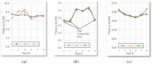
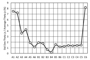
In each test, TIM II was deposited on the heat sink and thinned to 70 μm thickness using a flat spatula. The thickness was controlled by using two strips of Kapton tape placed on each side of heat sink to create a standoff that supported the TIM II application process. Weights applied to the insulation plate provided a downward force between the package and the heat sink. The weight was adjusted for each package based on the exposed area of each package. The CABGA has a small exposed area, therefore only a 0.5 kg mass was needed. Thetajc data are shown in Figure 4 as a function of the package number and engineer (1, 2 or 3). The standard deviation divided by the average of data taken by the three engineers for that package are shown in Figure 5. In general, the agreement between engineers for all packages is quite good. For most packages tested, the standard deviation between engineers is less than 2% of the average. Thetajc measurement for part C6 appears to be an outlier. The CABGA package showed greater deviation, especially for parts 1-4. This is not surprising because the CABGA with its small body size will be more susceptible to TIM II application variations compared to all other packages.
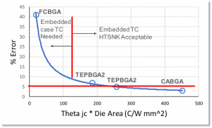
An analysis was conducted to determine a critical Thetajc value for which the case temperature should be measured with an embedded thermocouple. This analysis was based on an assumed level of 5% uncertainty in Thetajc measurements due to the TIM II resistance contribution. A corrected case temperature measurement can be written in Equation (2), using the portion of the power dissipated by the die.
(2)
Substituting Equation (2) into Equation (1) yields:

When the heat sink temperature is used as the case temperature reference, the TIM II resistance must be less than the acceptable uncertainty. The critical Thetajc value may be calculated in Equation (4).

where BLT is the bond line thickness and KTIM II is the thermal conductivity of TIM II. Theta TIM II may be approximated conservatively in Equation (4) by setting the heat transfer area equal to the die area. This is somewhat conservative because the packaging materials above and around the die promotes thermal spreading thereby increasing the effective heat transfer surface at the case. By increasing the thermal conductivity of the TIM II, lower Thetajc packages may be tested with the embedded thermocouple heat sink. For this study, the silver-filled grease selected as the TIM II material has a reported thermal conductivity of 9 W/m-K. For these calculations, a more conservative estimate of 8W/m-K was used for the TIM II thermal conductivity. A BLT thickness of 50 μm was assumed. Solving for Thetajc * ADie in Equation (5) yields an approximation for the critical limit when a heat sink with an embedded thermocouple may be used to measure Thetajc.

The error in Thetajc measurements made with a thermocouple inserted in the heat sink is plotted in Figure 6 as a function of Thetajc * ADie. At large Thetajc * ADie, the error is less that the 5% target, see for example the CABGA package. However, when Thetajc * ADie is smaller than 125 C/W*mm2, the error becomes quite large. The FCBGA package will require thermocouples mounted into the case.
Figure 6. Case measurement method based on Thetajc value.
CONCLUSIONS
The conditions for reproducibility presented here are considered as an initial study in the variability in measurements attributed to the test engineer. The variability in data attributed to the test engineer (as judged by one standard deviation) was approximately 2% of the Thetajc value for most of the packages tested. A more general study of variability would require each test engineer to calibrate temperature sensors, reattach thermocouples, and use their own cooling system. When a high conductivity TIM II material is selected, e.g., silver-filled grease, an embedded thermocouple in a cold plate or CPU cooler may be used to approximate the case temperature if the Thetajc value multiplied by its die area is larger than 125°C/W mm2. The FCBGA and higher conductivity TEPBGA2 package required an embedded thermocouple mounted to its case. The lower conductivity TEPBGA2 and the CABGA packages did not require embedded case thermocouples to measure Thetajc.
REFERENCES
[1] Lasance C. and Lacaze C., “A transient method for the accurate measurement of interface thermal resistances,” Semiconductor Thermal Measurement and Management Symposium, 1996, SEMI-THERM XII Proceedings, pp. 43-50
[2] JESD51-14, “Transient Dual Interface Test Method for the Measurement of the Thermal Resistance Junction-To-Case of Semiconductor Devices with Heat Flow Through a Single Path,” November 2010, https://www.jedec.org/standardsdocuments.
[3] Galloway J. and Okpe T., “Challenges in Measuring Theta jc for High Thermal Performance Packages,” Electronics Cooling Design, Number 2, Test & MeasurementTest & Measurement, Volume 20, May 29, 2014, https://www.electronics-cooling. com/2014/05/challenges-measuring-theta-jc-high-thermalperformance-packages.
[4] De Los Heros E., Galloway J., and Xu G., “Repeatable Surface Temperature Measurements Under High Heat Flux Conditions,” Advanced Technology Workshop on Thermal Management, 2014, Los Gatos, CA.
[5] JESD51-1, Integrated Circuit Thermal Measurement Method – Electrical Test Method (Single Semiconductor Device), December 1995.
