Authored by: Tejas Manohar Kesarkar and Nitesh Kumar Sardana
Abstract— Modern day electronics work in varied thermal conditions. The increase in demand of electronics has led to miniaturization, use of plastic housing, and more applications from the existing electronics in the market.
The model for analysis consists of multi-layered Cu-FR4 Printed Circuit Board (PCB) with a power dissipation of 10 W (Volumetric distribution in PCB). The PCB is further enclosed in a housing. Representative internal air temperatures are estimated for evaluating thermal performance of housing in different studies. The dimensions of housings used for these studies are similar to that of typical automotive electronics.
In the first study, an evaluation is carried out to understand the effect of orientation of metallic electronic housings w.r.t. incident airflow. Metallic housings are usually provided with heatsink and fins and the same are considered in our model. It is observed that the internal air temperature of the housing is minimum when the airflow is aligned in the direction of length of fins. It is also observed that an equally favorable orientation is when the airflow is directed on top of fins.
Another study is done to evaluate the effect of orientation of metallic and plastic housings w.r.t. gravity in case of natural convection airflow. Unlike metallic housing, plastic housings are usually devoid of fins and heatsinks. For both metallic and plastic housings, it is observed that the internal air temperature is minimum when the plane of the housing is vertical. Moreover, for metallic housings best orientation is when fins are aligned vertically.
In addition, a study to evaluate the effect of orientation of plastic housing w.r.t. incoming solar radiation in case of natural convection airflow is done. It is observed that internal air temperature is minimum when the plane of the housing is vertical.
All these observations are made from steady state thermal simulations carried out using FloTHERMTM. The ambient is considered to be similar to any electronics mounted in an automotive. In addition, all the three modes of heat transfer i.e. conduction, convection and radiation are considered.
This study will help forming guidelines for any design engineer, who wishes to choose an optimum orientation of housing, taking into account thermal performance of electronics.
Keywords— Electronics cooling, Mounting Orientation, Thermal Analysis, Thermal Management, ECU, Thermal Optimization, FloTHERM
Nomenclature
| T | Temperature, °C |
| ΔT | Temperature difference, °C |
| Rth | Thermal resistance, K/W |
| Rc-r | Ratio of heat transfer by convection to heat transfer by radiation from electronic housing to ambient air |
| Q | Total heat generation in ECU, W |
Subscripts
| i | Internal air of electronic housing |
| a | Ambient air around electronic housing |
| i-a | Between internal air and ambient air |
I. Introduction
Use of electronics is on the rise, especially in modern day automobiles. In general, the functionality of electronics has increased, posing challenges for the thermal management of electronics [1]. To make the electronics more reliable it is crucial to minimize the internal air temperatures of these electronic housings. Operating temperature usually has the highest impact on electronic component life and reliability – the rule of thumb in electronic product design is that every 10 °C rise in temperature decreases the average life by 50 percent. During development phase, designers may be poised with different options for mounting of the electronic housings. The study done in this paper will help setup guidelines that would allow a design engineer to choose an optimum orientation of housing in order to minimize internal air temperature of the same.
II. Modeling details
A. Product details
The product considered for analysis is an Electronic Control Unit (ECU) used in automobiles to control various systems. These ECUs have either metallic or plastic housings. Housing consists of a Printed Circuit Board (PCB) and heat dissipating components over it [2]. The PCB is further provided with connectors for external communication. Typically, metallic variants of the housing are provided with heatsinks. Each heatsink is in contact with PCB via a layer of Thermal Interface Material. This assists in heat transfer from PCB to external ambient by provision of a direct conduction path. On the outer surface of these heatsinks, fins are provided to increase exposed area of the housing. This increase in exposed area will result in lower convective and radiative thermal resistance of the housing. Plastic variants of the housing lack heatsinks and fins because of poor thermal conductivity of plastic.
B. Simulation model
Fig. 1 Simulation model: (a) Metallic housing with heatsink and fins (b) Plastic housing
Steady state thermal simulations were carried out in FloTHERMTM. All three modes of heat transfer, i.e. conduction, convection and radiation were considered. PCB was modeled as a lumped cuboid with equivalent orthotropic thermal conductivity of an automotive standard PCB. For simplicity of the model, connector was not considered as part of the geometry. The size of housings under study were similar to those of typical electronic housings used in automotive applications. The length and breadth of housings were modeled to be equal. Metallic housings were considered to be made of standard aluminum die cast material. Plastic housings were considered to be made of Polyamide-66 material. The value of emissivity for Polyamide-66 was considered significantly larger as compared to that of Aluminum die cast material. Fig. 1 shows metallic and plastic housing models used for simulation. For metallic housing, the two heatsinks were considered to be of unequal surface areas. For plastic housing, the top cover was considered to be of greater height than bottom cover.
An ambient temperature (Ta), which is typical in automotive application, was used for the simulation. In the study concerning incident airflow, velocity of incoming air was assumed to be 2 m/s, which is as per automotive standard.
C. Thermal loads on ECU
A total heat generation of 10 W caused by power losses in components is spread evenly over PCB volume. Further, in one of the studies, effect of solar radiation is considered. For worst-case analysis, conditions of 12 noon of June 21, for latitude of 12.97 °N (Bangalore), were used to calculate solar load on ECU.
D. Simulation and measurement correlation
Before conducting the following studies, results from simulation model for plastic housing were correlated with real time measurements of an existing product. The comparison of Rth,i-a for plastic housing from simulation and experiment is shown in Fig 2. Rth,i-a is calculated as follows:

Since simulation results were found to be within 4% of the measurement results, it can be assumed that the model is realistic.
Fig. 2 Comparison of Rth,i-a for plastic housing from simulation and experiment
III. Analysis of results
Lifetime of electronic components depends on the internal air temperature (Ti) of the housings. This is why, the temperature rise of internal air over ambient temperature i.e. temperature difference between internal air and ambient (ΔTi-a) was chosen as the parameter for comparison of different orientations in the following studies. For the estimation of Ti one can use either of following two approaches. The first approach is to use an average value from temperature probes placed within the internal volume of housing. The second approach is to estimate Ti by generating iso-surfaces. For the results presented in the following sections, the latter approach was used. However, the conclusions remain the same irrespective of the approach used.
For first study, forced convection airflow was considered. For rest of the studies, natural convection airflow is considered around the housing.
A. Effect of orientation of metallic housings w.r.t. incident air flow
In this section we study the effect of different airflow directions (as shown in Fig. 3) on ΔTi-a of metallic housings. This study is applicable for electronic housings placed in forced airflow environments e.g. ECUs placed behind radiator fans. In this study, for all airflow directions, the plane of the housing is assumed to be horizontal i.e. perpendicular to gravity as shown in Fig. 3.
Fig. 3 Different airflow directions for metallic housing
The temperature rise of internal air (ΔTi-a) for the six directions of airflow is given in Table. I. It was observed that ΔTi-a is minimum when airflow is aligned with the length of fins i.e. for direction A. This is a result of air being allowed to flow freely in between the fins, which in turn improves convective heat transfer. This phenomenon is shown in Fig. 4. An equally favorable direction of airflow is direction E. This is because when air is directed at fins from top, it is able to move freely in between the fins. The airflow for direction E is shown in Fig. 5. For direction B, as can be seen in Fig. 6, because of flow separation, air velocity between the fins is very low. This reduces the effectiveness of fins, thus leading to larger rise in temperature of internal air. The internal air temperature plots for directions A and E are shown in Fig. 7 (a)-(b).
Table 1. Rise of internal air temperature for different orientations of metallic housing w.r.t. incoming airflow
Fig. 4 Direction A of airflow for metallic housing. Speed contour plot
Fig. 5 Direction E of airflow for metallic housing. Speed contour plot
Fig. 6 Direction B of airflow for metallic housing. Velocity vector plot.
Fig. 7 Internal air temperature (Ti) of metallic housing for directions A and E of airflow
B. Effect of orientation of metallic housings w.r.t. gravity
The effect on ΔTi-a of different orientations of metallic housings w.r.t gravity direction (as shown in Fig. 8) is studied.
Fig. 8 Different orientations of gravity w.r.t metallic housing
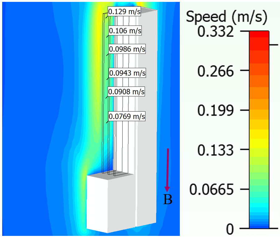
For the six orientations of gravity, the temperature rise of internal air (ΔTi-a) is given in Table II. It was observed that ΔTia is minimum for direction B of gravity i.e. when the fins are aligned vertically and the heatsink area lies near the top. This is because of better heat transfer by convection as air rises freely in between the fins. The air stream built up for direction B is shown in Fig. 9 (a)-(b). The internal air temperature plot for direction B of gravity is shown in Fig. 10.
Fig. 9 Direction B of gravity for metallic housing: (a) Velocity vector plot (b) Speed contour plot
Table 2. Rise of internal air temperature for different orientations of metallic housing w.r.t. gravity
Fig. 10 Internal air temperature (Ti) of metallic housing for direction B of gravity
C. Effect of orientation of plastic housings w.r.t. gravity
In this section we study the effect on ΔTi-a of different orientations of plastic housing w.r.t gravity direction (as shown in Fig. 11). Based on geometry description, directions A and B are different.
Fig. 11 Different orientations of gravity w.r.t plastic housing
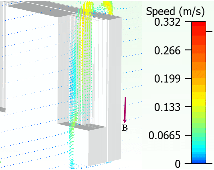
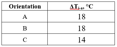
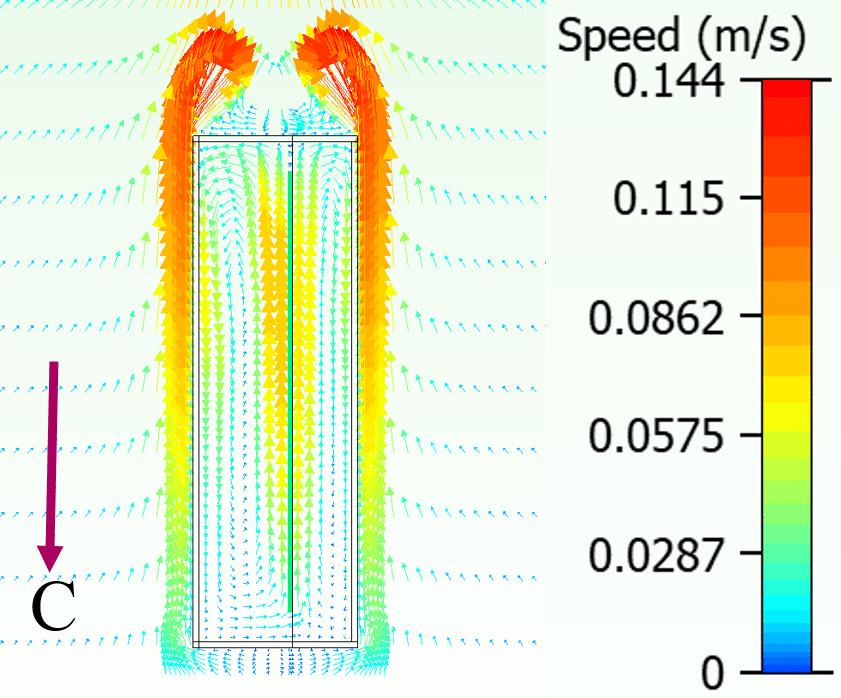
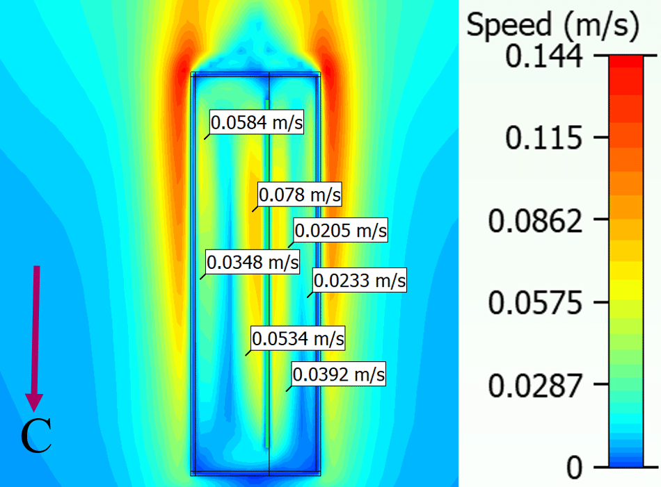
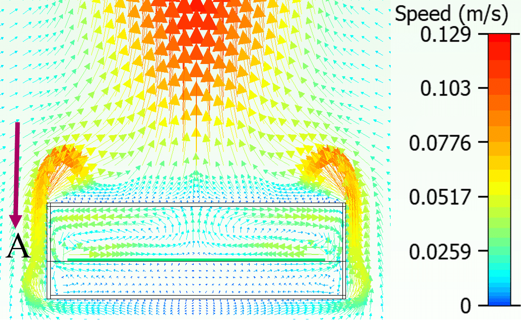
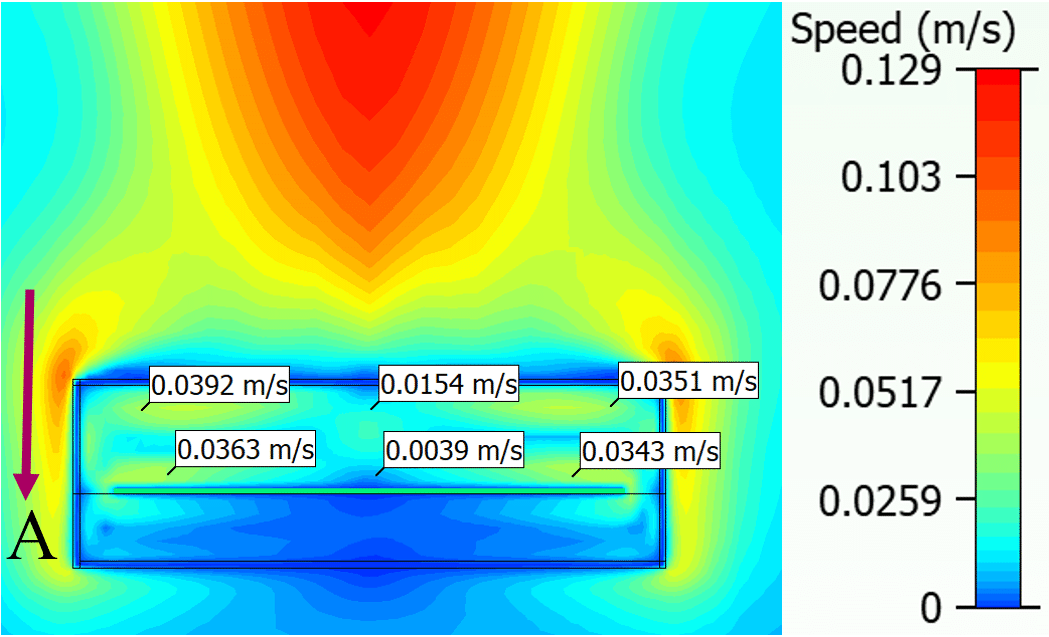
The temperature rise of internal air (ΔTi-a) for the three given orientations of gravity is given in Table. III. It was observed that ΔTi-a is minimum for direction C of gravity i.e. when the plane of the housing is vertical. As shown in Fig 12 (a)-(b), for direction C i.e. when plane of ECU is vertical, the column of rising hot air near the PCB accelerates to gain higher velocity as it comes in contact with the entire length of the PCB. Higher momentum leads to better heat transfer by convection. For direction A, as shown in Fig 13 (a)-(b), the vertical movement of air is restricted. In addition, the rising hot air comes in contact with shorter length of PCB. This causes poor air movement, thus leading to less effective heat transfer by convection. Similar phenomenon is observed for direction B. The internal air temperature plot for direction C of gravity is shown in Fig. 14.
Table 3. Rise of internal air temperature for different orientations of plastic housing w.r.t. gravity
Fig. 12 Direction C of gravity for plastic housing: (a) Velocity vector plot (b) Speed contour plot
Fig 13. Direction A of gravity for plastic housing: (a) Velocity vector plot (b) Speed contour plot
Fig 14. Internal air temperature (Ti) of plastic housing for direction C of gravity
D. Effect of orientation of plastic housings w.r.t. solar radiation
The effect on ΔTi-a of different orientations of plastic housings w.r.t solar radiation (as shown in Fig. 15) is studied. In addition to heat generation of 10 W, solar radiation is considered, details of which are mentioned in section I-C. This study is applicable for electronic housings mounted in environments exposed to solar radiation e.g. ECUs mounted on outer body of an off-road automotive.
Fig. 15 Different orientation of plastic housing w.r.t solar radiation
For given two orientations the temperature rise of internal air (ΔTi-a) is given in Table II. It was observed that ΔTi-a is minimum for case (b) of Fig. 15 i.e. when the plane of the housing is vertical. This is a result of lesser projected-area perpendicular to direction of solar radiation. The internal air temperature plots for the two different orientations are shown in Fig. 16 (a)-(b).
Fig. 16 Internal air temperature (Ti) of plastic housing for different orientation w.r.t solar radiation. Note that arrows show direction of solar radiation
IV. Conclusion
The internal air temperature (Ti) of an electronic housing is a critical indicator of the lifetime of that electronic product. Certain orientations of the housing result in lower ΔTi-a as compared to others. For metallic housings under incident airflow, least ΔTi-a is achieved either when airflow direction is aligned with the length of the fins or when airflow is directed towards top of the fins. For metallic and plastic housings under natural convection airflow, ΔTi-a is minimum when the plane of the housing is vertical. Moreover, for metallic housings ΔTi-a is minimum when the fins are vertical and heatsink areas lie towards the top. In addition, when solar radiation acts on plastic housings least ΔTi-a is observed when the plane of the ECU is vertical.
For same orientation of plastic housing w.r.t. gravity, it was observed that ΔTi-a increases by 17 °C with addition of solar load on the housing. This shows that it is important to consider the effect of solar radiation for relevant applications.
For natural convection airflow, ratio of heat transfer by convection to heat transfer by radiation (Rc-r) is studied. For metallic housings, Rc-r is observed to be approximately 2:1. For plastic housings, Rc-r is found to be approximately 1:3. This shows that radiation is a major mode of heat transfer in case of plastic housings. Therefore, surroundings of the mounting location also play a critical role in case of plastic housing. Whereas, for metallic housings, the airflow around the electronics plays a critical role.
The studies carried out in this paper can help design engineers in choosing an optimum orientation for their electronic products.
Acknowledgment
We are very grateful to our organization, Robert Bosch Engineering and Business Solution Pvt. Ltd., for giving us an opportunity to conduct this research. We are also grateful for the assistance provided by our family, friends and colleagues towards writing this paper. Special thanks to Sarvesh Talaulicar, Vipindas Othiyil and Lakshmikanth G for giving us necessary approvals to present this paper in the conference.
References
- Nitesh Kumar Sardana, Susyamala Pavan Kumar Busam, Dr. Laxmidhar Biswal, “Simulation Driven Design Optimization for Reduction of Temperature on a High Current Density PCB,” International NAFEMS Conference on Engineering Analysis, Modeling, Simulation and 3D-Printing (NAFEMS-3D) – 2016
- Nitesh Kumar Sardana, Ritwik Alok Pattnayak, Susyamala Pavan Kumar Busam, Chandan Kumar Ghosh ,and Laxmidhar Biswal, “Thermal Analysis of a battery in an electronic device for an outdoor application,” ICEP 2016 Proceedings
Authors
Tejas Manohar Kesarkar
RBEI/EAX
Robert Bosch Engineering and Business Solutions Pvt. Ltd.
Bangalore, India
TejasManohar.Kesarkar@in.bosch.com
Nitesh Kumar Sardana
RBEI/EAX
Robert Bosch Engineering and Business Solutions Pvt. Ltd.
Bangalore, India
Niteshkumar.Sardana@in.bosch.com


