When you’re planning how to solve the ongoing problem of keeping things cool enough, it’s easy to mentally blur the lines between hot components and hot boxes. The difficulty is that the solution for one of these may not be adequate or appropriate for the other.
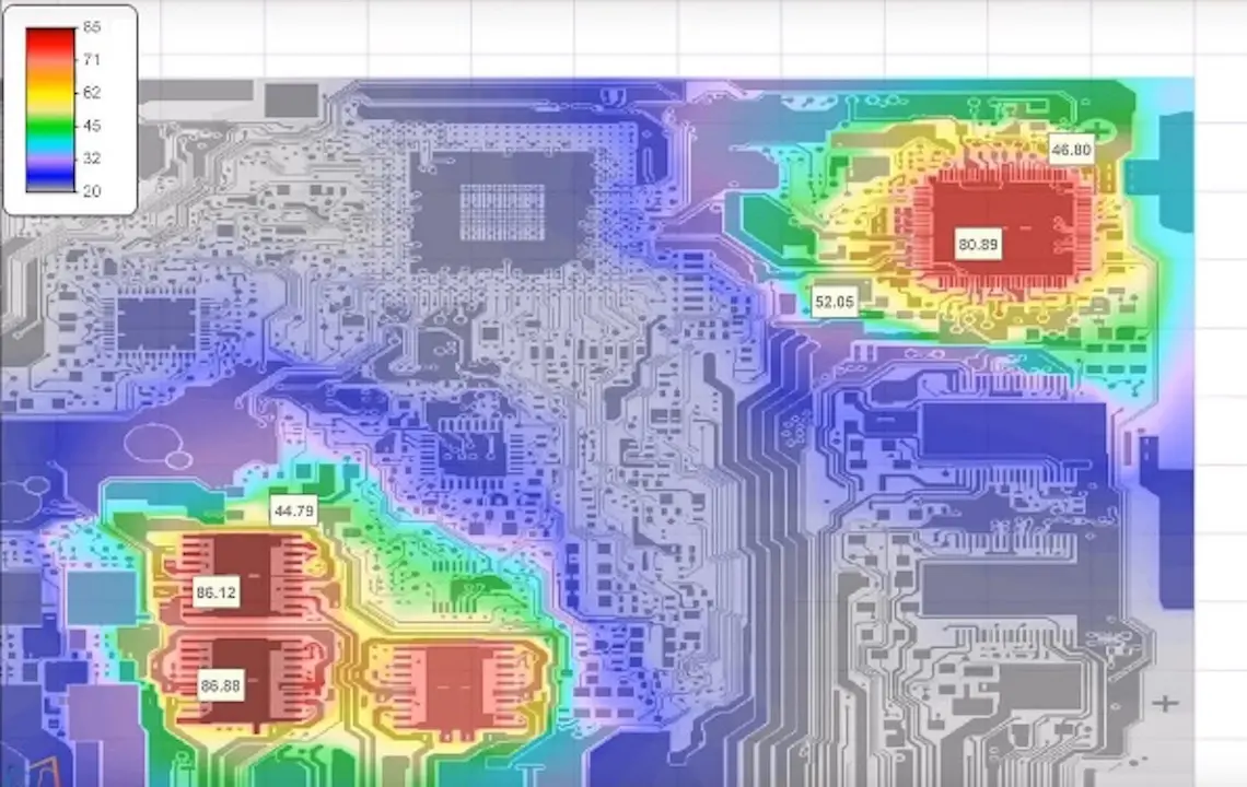
Here’s the situation: in most systems, the heat sources are not distributed uniformly across the circuit board or throughout the end-product. In most cases, there are one or more highly localized sources of heat, such as power supplies, large processors or other ICs, power devices such as MOSFETs and IGBTs, and even passive components such as resistors (see Figure below).

As a consequence, it’s simplistic to assume that everything will be OK when the average temperature of the box is below the acceptable maximum, as that comforting number can be misleading. It’s entirely possible for the temperature at those spot heat sources to be higher than that average, having inadequate cooling due to restricted air flow and shading from nearby components. Besides those issues, there’s an even more insidious impediment to proper cooling, when each device assumes it has sole or primary access to the PCB copper for cooling purposes, conveniently ignoring the fact that nearby components are also trying to use it for their dissipation. No one has these “heat highways” all to themselves these days.
The first task for the designer is to identify those sources and keep them below their maximum temperature specification. How far below depends on both reliability and performance concerns, especially for components which have drift in key specifications due to their parameter temperature coefficients. Analog and passive components are, of course, the most sensitive to temperature changes, but even digital ones will see shifts in performance and margins as the temperature increases (you did study the data sheets to check specifications at the extremes, right?).
To keep these hot spots cool, the designers must reach into mixed bag of resources, using a combination of heat sinks, thermal paths, heat pipes, forced air or even liquid cooling schemes, blending the well-known cooling mechanisms of conduction, convection, and radiation. How to mix those, and how much of each is actually available, is a function of the design, the environment and the operational scenario (in the vacuum of space, there is no conduction or convection to the “outside,” of course; it’s all radiation).
Keeping a system with localized hot spots cool is an ongoing battle and balance. The hotter the overall temperature, the more difficult it will be to keep that local spot cool, since the temperature differential is reduced. At the same time, the local spot is contributing to the overall heat load.
In the non-engineering social world, we’re often told that we must balance the needs of the many versus the needs of the few. If a “few” occasionally have to get the shorter end of the stick, as the cliché goes, that’s deemed an acceptable tradeoff. But in engineering design, that guideline usually doesn’t hold true. Certainly, design is largely about finding an acceptable balance point or sweet-spot among any options and tradeoffs while meeting (or compromising) on objectives and priorities, but it is not acceptable for one component to get too hot while the others are within spec.
The solution is found in the usual back-and-forth of engineering design. Yes, we try to get those hot components cooler by using lower-dissipation parts when possible, as a first step. Unfortunately, that is often not a possible option. Fortunately, today’s CFD modeling and analysis tools make the task of investigating the “what if?” options and assessing the tradeoffs a much easier task than it was in the not-so-distant past.
As a result, it’s back to the tactics of increasing airflow, improving airflow paths, and bigger and better heat sinks (you can never have one that’s too big!) as starters. Or perhaps it calls for even redoing the board and system layout (if possible) to spread these local heat sources, or even doing the opposite and concentrating them so a higher-intensity local solution can be applied. The key is to keep both the local and global needs in mind at the same time, and that’s usually not easy.
Image sources:
Fig 1: https://www.multi-circuit-boards.eu/en/support/thermal-management.html


