ABSTRACT
Cooling fan noise is a system property determined as much by thermal and mechanical design and fan selection as by a fan’s acoustical design. While even the quietest fan can be used in a noisy manner, a significant fraction of unpleasant surprises can be avoided.
NOMENCLATURE
C Numerical constant
D Impeller diameter [m]
cP Specific heat [J/(kg ºK)]
AD Reference duct area (1 sq. meter)
I Installation Effects [dBA]
KWA Specific Sound Power Level [dBA]
LWA Sound Power Level [dBA]
N Rotation speed [s-1]
qH Heat generated [W]
PS Static pressure rise [Pa]
R Backpressure coefficient
TX, TI Exhaust and inlet air temperatures [ºC]
V Flowrate [m3/s]
∆KWA Change in Specific Sound Power Level [dBA]
ξ Bypass ratio
φ Non-dimensional flow coefficient= /(.078ND3)
φ0 Optimal non-dimensional operating point
ρ Air density [kg/m3]
INTRODUCTION
Interest in and concern about cooling fan noise is increasing due to increasing power density, decreasing package size, and greater customer sensitivity to noise. It’s not uncommon for thermal engineers to find themselves with a late prototype system that doesn’t meet noise emission goals, necessitating a search for a “quiet fan”. This quest is often perplexing, because fans that were quiet in a similar product or application, or appear to be quiet in a catalog, often don’t deliver the hoped-for performance.
The insight needed to achieve quiet fan cooling is found at the intersection of acoustics and thermal engineering. Cooling fan noise emission is a system property influenced as much by the thermal design including heat generation, conduction, and exchange, as by the “quietness” of the fan.
The bad news is that certain early design decisions can unwittingly “bake” noise into a system. The good news is that such outcomes can be foreseen, and a noise-conscious design process can increase the likelihood of success.
NOISE EMISSION OF COOLING FANS
Five major factors determine the noise emission of an air mover. These are joined in a simple empirical equation for A-weighted sound power level LWA [1,2]:
LWA= 50 log + 20 log R + KWA (ϕ0 ) + ΔKWA (ϕ) + I + C (1)
where C is -4 for flowrate in m3/s and -185 if in cfm. In either case, standard atmospheric density and a reference duct area (AD) of 1 square meter are assumed.
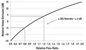
The first factor in Equation 1 is a direct consequence of the thermal design, which determines the required flowrate:

Flowrate, in turn, depends upon many factors that thermal engineers regularly manage including heat rejection (qH), bypass flow ratio (ξ), heat exchanger design (TX – TI), and inlet air temperature TI.
Changes in the thermal design that alter the required airflow can influence the likely noise emission by several dB.
Figure 1: Relative noise emission vs. flowrate
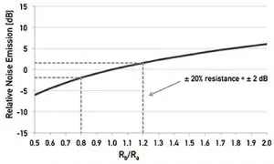
The second factor is the non-dimensional, turbulent-flow chassis backpressure coefficient R, determined from:

Changes in backpressure can also influence the likely noise emission (see Figure 2 following).
Figure 2: Relative noise emission vs. backpressure coefficient
The third factor expresses the fan’s intrinsic noisiness in terms of its “specific sound power level” KWA, which applies at its quietest operating point (near maximum static efficiency). Typical axial fan KWA values are around 60 with “quiet” and “noisy” fans ranging 10 dBA below and above this average, respectively. Centrifugal blowers and centrifugal fans can be significantly quieter than axial fans (6 and 15 dB lower respectively on average); but may not fit well into systems designed around axial fans.
The specific sound power level KWA is determined from LWAat each operating point as (2,3)

KWA values depend on the units of flow and pressure used to generate them. Care should be taken that they are used consistently and not mixed in equations with other flow and pressure units.
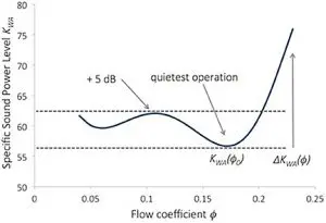
The fourth factor addresses the fact that a fan emits additional noise when it is not well matched to the load (non-optimal operating point). Figure 3 shows an example of a typical fan in which this factor can cost 5 dB or more.
The fifth factor combines several less-predictable factors brought about by installing the fan into a real system. These typically include inlet flow distortions such as uneven flow distribution and turbulence ingestion, as well as partial shielding of the fan by the chassis. Flow distortions change the interaction between streamlines and fan blades that can increase the effective KWA and reduce flow delivery. In such a situation the fan speed has to be increased to produce the required flow, resulting in yet more noise being generated.
Figure 3: Typical KWA(φ) vs. operating point
Taken together these five factors can explain many otherwise surprising disappointments. The demands placed upon a fan by the thermal and mechanical designs are at least as important as the acoustical design features of the fan. Even the quietest fan could be rendered noisy if implemented poorly or operated at high speed. Conversely, a rather ordinary fan can appear to be “quiet” when it is used well in a less-demanding system.
CONSEQUENCES FOR DESIGN
Design engineers already possess the skills needed to make fan-cooled systems quieter, even without any knowledge of acoustics. Yet the constraints of typical projects often lead them to unwittingly design high noise levels into their products. These decisions usually occur very early in the design process, and it’s not always possible to overcome them later by finding a “silver bullet” quiet fan. Because of the intertwining nature of thermal and mechanical design with noise, an integrated approach is necessary to achieve success.
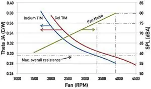
Even apparently minor and unrelated design decisions can be important. In one example [3], a less thermally resistive TIM reduced by 15% the airflow requirement for a CPU/ASIC package. The minimum fan speed for adequate cooling decreased from 3900 to 3300 RPM, and the noise emission dropped with it by about 5 dBA.
Figure 4 shows the effective thermal resistance (blue and red lines) vs. RPM for the two TIM materials, with a target overall resistance of 0.295 ºC/W. The green line shows sound pressure level (dBA, right axis) for the two RPMs and the resulting noise reduction.
In another example, design review of a large and unexpectedly loud server rack revealed that it was 19 dBA louder than necessary. Of this, only 4 dBA was due to a higher-KWA fan. Poor load-matching and avoidable flow blockages accounted for another 4 dBA. The remaining 11 dBA was directly related to poor heat exchanger efficiency and excessive thermal resistance. [1]
Figure 4: TIM Selection vs. Noise Emission (adapted from [3])
RATINGS
It has long been customary to rate fan noise according to its A-weighted sound pressure level, 1 meter upstream along the rotational axis, suspended in a hemi-anechoic chamber. It’s a straight- forward but highly unrealistic setup: the fan is subjected to no load and interacts with pristine inflow and outflow conditions.
More meaningful data can be obtained from measurements according to ISO 10302 [4] (for small fans) and ISO 13347 [5] (for larger fans). The global sound power level is measured under various realistic load conditions simultaneously with aerodynamic performance. Some fan manufacturers are beginning to include A-weighted sound power level data in their catalogs; more detailed acoustical analysis (e.g., tonality) is also possible and such data may also be available. Best of all, realistic inlet and outlet conditions can be mocked up to better simulate critical applications.
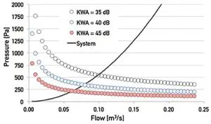
Equation 4 can be inverted to anticipate noise-related constraints. For example, we can plot the locus of pressure-flow states for candidate fans with KWA of 35, 40, and 45 (dBA), that just deliver a maximum permissible 80 dBA sound power level. The system curve is laid across these loci (500 Pa @ 0.1 m3/s). The points of intersection represent the maximum flow achievable within the noise constraint for each case, approximately 0.100, 0.075, and 0.60 m3/s, respectively. This illustrates both the benefit of quiet fans and the ability to infer thermal and mechanical design goals.
Figure 5: Pressure-flow combinations that meet 80 LWA
CHARACTERISTICS OF QUIET AXIAL FANS
Low-KWA axial fans cannot be reliably identified based on how they look. Only acoustical data can answer that question. Certain visible characteristics are common in quiet fans, but may not by themselves guarantee quiet operation. Other subtle characteristics may actually be more important.
Aerodynamic blade design: Laminar airflow is quietest. Blades that change their pitch (twist) and chord (width) between hub and tip promote laminar flow by managing the relative vector velocities of the incoming airflow and advancing blade.
Tip gap: Close machining tolerances permit a tight gap between tip and shroud. Air that backflows around the tips creates noise and also requires that the fan is sped up to recover the lost airflow [6].
Curved vs. Straight blades: A curved leading edge may help reduce the relative strength of blade pass tones.
Serrated trailing edges reduce noise by disrupting the uniformity of the air leaving the trailing edge, but trailing edge noise is only one of several mechanisms of fan noise generation.
Stacked fans: are popular in systems with high backpressure. The downstream (secondary) fan ingests spiraling, turbulent discharge airflow from the primary. In co-rotating fan pairs, the secondary fan blades chase the flow and generate the same or more noise but scant additional airflow. A flow straightener (or a wide gap) may allow an identical secondary fan to perform as if it were independent. In counter-rotating pairs, the secondary fan usually looks noticeably different in order to efficiently handle the spiraling inflow. Systems that require stacked fans are potential candidates for conversion to centrifugal formats.
Fan dimensions: Fan dimensions have an indirect bearing on noise emission because they influence the compatibility with the system through the ideal operating point. Diameter, thickness, and hub ratio all play a role. All things being equal, thin- ner axial fans deliver less flow than thick ones, and large hubs are optimized for higher pressure than small ones.
CONCLUSION
- No fan is so quiet that it can be relied upon to save a noisy system after the fact
- Baseline noise emission is determined by the thermal and mechanical designs as well as the space allotted for the fan and its assigned format (axial, centrifugal).
- Sound power level (LWA) data obtained at representative loads is more meaningful than unloaded, on-axis sound pressure level data
- A low-KWA fan, selected to match the system operating point, and implemented with minimal installation effects, gives the best results
- Quiet operation and low energy consumption go hand in hand
- You can’t tell if a fan is quiet by how it looks
- Two fans that look identical need not have the same performance and noise emission
- Just because a fan was quiet in another system doesn’t mean it will be quiet in your system
- Just because a fan was quiet in last year’s system doesn’t mean that it will remain quiet if heat generation increases.
- All things being otherwise equal, fan noise goes as 50 log (RPM).
REFERENCES
- Nelson, Reducing noise by managing heat, Proceedings of Noise Con 2016.
- Nelson, In Search of a Quiet Fan, Proceedings of 34th IEEE Semi-Therm Symposium, 2018.
- Vogel, J. Galloway, D. Nelson, “Improved router & server OPEX, acoustics and leakage power through advancements in ASIC/CPU design”, Proceedings of 32nd IEEE Semi-Therm Symposium.
- ISO 10302 – Acoustics – Measurement of airborne noise emit- ted and structure-borne vibration induced by small air- moving devices – Part 1: airborne noise
- ISO 13347 – Industrial Fans – Determination of fan sound power levels under standardized laboratory conditions
- Beltman, The Airflow and Acoustic Performance of current 92mm system fans, Proceedings of Noise Con 2003.

