INTRODUCTION
Graphite is a naturally occurring form of pure carbon in which the atomic bonds interlock in the layers of a two-dimensional molecular sheet. In nature, dense, rigid graphite ore is mined, purified, and processed into numerous applications, including the inexpensive flexible natural graphite sheets used in electronics. The ore is mechanically reduced and then reconstructed into flexible sheets that typically range from 40µm to several millimeters in thickness. Because of this alignment process, the ability to conduct heat both in-plane and thru-plane can be engineered to the final application, such as heat spreader, heat shield, or thermal interface material (TIM). Chemical vapor deposition is a precise, but relatively expensive, means of assembling carbon atoms into highly oriented pyrolytic graphite (HOPG) in a controlled atmosphere. HOPG tends to be rigid and many millimeters in thickness. For the high volume manufacturing used in electronics, methods have been developed to synthesize thin flexible graphite heat spreaders from polymers. These techniques produce sheets on the order of 10 to 50µm, fully compressed, although less dense versions used as thermal interface materials are available. The thinnest form of graphite, graphene, is a planar carbon molecule one or two atoms thick. Because all flexible graphite is pure carbon, it remains flexible hundreds of degrees above and below ambient, so its practical application in electronics is limited only by the adjacent materials such as adhesives and dielectrics.
SIMPLE ORTHOTROPIC CALCULATIONS
The Scale of Graphite Thermal Orthotropy
For most electronics-scale applications, both natural and synthetic graphite foils present as homogeneous, orthotropic solids. Synthetic graphite sheets, in particular, remain homogeneous down to the molecular level, to the point that they are used as monochrometers in X-ray diffraction studies. In contrast, natural graphite foils are compressed from graphite flakes [1] and contain varying degrees of anisotropy below one-quarter millimeter length scales. The thermal properties needed for steady state calculations (thermal conductivity) and for transient calculations (heat capacity and density) vary measurably with grade, thickness, and operating temperature. Because the thermal conductivity is measured at room temperature, a correction may be applied for electronics-opera- ting temperatures. In particular, some graphite vendors rate their products based on room temperature measurements, while others rate them based on operating temperature calculations [2].
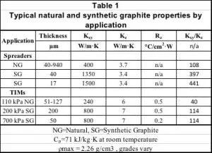
An important scale for modeling graphite is the ratio of thermal conductivity in-plane to thru-plane. Grades are manufactured according to their intended use, but most grades have more than 100 times the thermal conductivity in-plane to thru-plane. Table 1 shows some representative values.
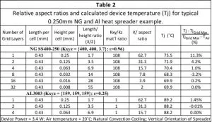
Two challenges arise from these extreme ratios; both the accuracy of the answer and the reliability of convergence will be challenged. Table 2 shows the length-to-height ratios of the hexahedral grid elements taken from a model and the relative size compared with the thermal orthotropy of the graphite.
The takeaway is that a model meshed for graphite may not converge if used for metals, and vice versa, due to the distortion that results from the orthotropic thermal conductivity ratios. Moreover, a “smaller” or finer grid will not improve the accuracy; it is the aspect ratio of the elements near the source that drives the solution.
Grid Dependancy in a CFD Model
Low aspect ratio discretization is not a pure function of geometry as it is in isotropic materials, and a mesh suited for aluminum may not be optimized for graphite. In isotropic solids, a unit aspect ratio mesh is less likely to distort a calculation, and many automatic meshing algorithms do a fine job with isotropic materials. It is up to the modeler to determine whether the tool includes algorithms to automatically increase the mesh density in regions of high gradients, which may be coded differently for solid and fluid volumes. Due to the thin nature of graphite heat spreaders, substantial Z-axis magnification may be useful in viewing the model near the heat source for the modeler to observe the effect of discretization near the (expected) gradients. Magnifying only the through-thickness geometry, rather than zooming in, helps to retain perspective in these very thin layers. If the modeler exchanges an isotropic material property for a graphite material property, or vice versa, without re-gridding, the model may fail to converge. A provision for plate elements, which are included in some FEA software, may simplify this step in planar models.
To quantify the effect of the grid aspect ratios, a simple model was constructed and meshed identically for 250µm sheets of two heat spreading materials. Standard grades of graphite (SS400-250 [3]) and aluminum (3003-H14) were used to spread the heat generated by a surface-mounted electronic device.
Thermal Model
The thermal model was constructed, using commercial finite-volume CFD software.[4] Its details replicated the mounting of a single LED mounted atop a 50mm x 50mm x 250µm thick heat spreader. The 3.5mm heat source is bonded to the center of the graphite plate atop a dielectric material except for the thermal via. A polymer dome and quartz diffuser make up the top of the LED, and the base consists of GaN with material properties published by the manufacturer. [5,6] The test setup was described and was used for model validation in a separate publication.[7]
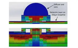
Figure 3 depicts the component geometry in cross-section with the calculated heat flux superimposed on it. The model was used to calculate component temperatures for a graphite material with an in-plane thermal conductivity 108 times that of the thru-plane value (Kxy/Kz = 108). Solutions were performed using grid cell sizes of varying aspect ratio.
Thermal Model Results and Discussion
Table 2 indicates the details of 6 iterations of the solution, which differed according to the number of grid layers in the graphite material and, consequently, the cell height. It also provides the calculated value of Tj (maximum heater temperature) and the % difference in Tj for each iteration, compared with the 32-layer solution, assumed to be the most accurate iteration. It also shows 3 iterations for an identical model, with the exception that the graphite is replaced by aluminum.
The highest temperature in the model, which fell within the square footprint of the heat load, was chosen as the junction temperature, and a point opposite it on the back side of the spreader was used as a touch temperature. The vertical plate was modeled in a laminar natural convection environment. Surface temperatures were sampled along the horizontal rather than vertical axis to reduce the influence of convection.
The grid layers in the space between the top and bottom planes of the heat spreader were manually specified, as were the planes normal to them bounding the footprint of the device. The mesher automatically added cells adjacent to the heat source, presumably due to the proximity of non-aligned edges in the under-meshed models, and round-off errors. A typical temperature error, shown as a percent difference from the most refined mesh, was calculated for Table 2. The results revealed insensitivity to grid layers in the aluminum control model, but decreasing temperature (spreading resistance) as the number of layers was increased in the graphite. For the junction temperature (Tj), the biggest return on computing memory to solution accuracy occurred when increasing from one to three layers, but a 2.3% error was still apparent in the case temperature with a four-layer mesh. This mesh induced error continued in the solder-point temperature atop the dielectric (Tsp), as well as in a touch temperature on the opposite side of the spreader (Ttouch). However, grid dependency did not appear on the surface 25mm away from the source.
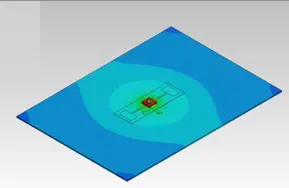
Figure 1 depicts temperature contours of the full model in a perspective view. The CFD capability of the software is used to calculate the cooling effect of buoyancy-driven natural convection air currents and the resultant temperatures on the components. It also shows the overall geometry of the LED device in contact with the two electrical pads on the substrate.
Figure 1. Physical configuration of model with LED atop electrical leads and dielectric layer on a large graphite spreader plate. Temperature contours are shown for a vertical plate orientation. Temperatures: Peak (Red) = 77.5˚C; Minimum (dark blue) = 56.9˚C; Air = 20˚C.
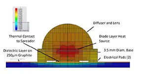
Figure 2 shows temperature contours mapped onto the device and spreader vertical cross-section. The graphite is meshed with 2 grid layers. As Table 2 indicates, the calculated value of Tj differs from the most refined model having 32 grid layers by 4.2% of the Tj temperature rise above the ambient air temperature.
Figure 2. Vertical slice through the thermal model with LED atop electrical leads and dielectric layer on a large spreader plate. Graphite meshed with 2 grid layers. Temperature contours are shown for a vertical plate orientation. Temperatures: Peak (Red) = 68˚C; Minimum (dark blue) = 48˚C; Air = 20˚C.
Figure 3 displays heat flux contours on the vertical cross-section of the component geometry. Here, the graphite has the maximum number of grid layers, equal to 32. The heat flux profiles in Figure 3 reveal that the spreading in the graphite extended to many times the thickness of the spreader and well beyond the heat source footprint. In this example, a single layer mesh will capture most of the spreading in the isotropic material.
Figure 3. Top: Vertical slice through the thermal model of an LED mounted on graphite spreader. Heat flux contours are shown. Graphite meshed with 32 grid layers. Bottom: Magnification (@ 5.3x) of the spreader in the z-direction reveals flux gradients within the graphite layer, that may aid in selecting an optimum grid layer thickness.
In order to capture the heat flux profile adjacent to the surface heat source, the analyst must balance the need for a high orthotropic ratio grid with a narrow grid that also captures the edges of the source. This two-dimensional drive for granularity may result in some very tiny, high aspect ratio cells directly adjacent to the source. Depending on the meshing or gridding technique, it may be useful to create an inset part in the spreader and impose a fine mesh on it locally.
CONCLUSIONS
Modeling graphite heat spreaders is within the capability of commercial software packages but the user needs to be aware of the unique capabilities and limitations of the numerical methods. High orthotropic-ratio flexible graphite heat spreaders and TIMs impart a more disproportionate thermal influence than their thin geometry would suggest. The validation of a thermal simulation should be accurate enough to distinguish differences in thickness and materials, and may require scrutiny of the energy balance within very fine structures that might otherwise be neglected. These high orthotropic ratios account for the occasional failure of models discretized for graphite to fail when converted to an isotropic material, and vice versa.
REFERENCES
- Shane, James, Robert J. Russell, and Raymond A. Bochman. “Flexible graphite material of expanded particles compressed together.” U.S. Patent 3,404,061, issued October 1, 1968.
- Beyerle, R., Smalc, M., Wayne, , & Reynolds III, R. A. (2013, July). “A Comparison of Methods to Measure the Thermal Diffusivity of Anisotropic Graphite Heat Spreaders.” In ASME 2013 International Technical Conference and Exhibition on Packaging and Integration of Electronic and Photonic Microsystems (InterPACK2013-73093). American Society of Mechanical Engineers.
- eGRAF®, SPREADERSHIELD™, and HiTHERM™, are trademarks of NeoGraf Solutions,
- FloEFD®, trademark of Mentor (Version = that current in December, 2014).
- Tseng, W., Getz, G., Fedor, B.S., Krassowski, D.W., 2000, “Anisotropic Graphite Heat Spreader for Electronics Thermal Management,” Proceedings, International PCIM/Power Quality Conference, Nuremberg, Germany, June 6, 2000.
- Norley, “The role of natural graphite in electronics cooling.” Technical Brief, ElectronicsCooling, Vol. 7, No. 3, August, 2001).
- Yin Xiong et al., “Thermal tests and analysis of thin graphite heat spreader for hot spot reduction in handheld devices,” 2008 11th Intersociety Conference on Thermal and Thermomechanical Phenomena in Electronic Systems, Orlando, FL, 2008, 583-590.

