Introduction/Background
The pace of development in the electronics and telecommunication fields has been accelerating in all aspects of the business. For example, electronics/telecommunications equipment has traditionally been housed in large buildings, smaller buildings (sheds) and outdoor cabinets. The introduction of electronics to the outdoor environment has imposed serious constraints on enclosure design since temperature and humidity are the two major causes of electronics failure. Since most electronic systems do not include environmentally hardened designs, the enclosure must provide an environment in which they can survive. Among the equipment/systems involved are displays such as LCD, LED and other monitors.
The use of LEDs (Light Emitting Diodes) has been increasing exponentially in the last few years. In the beginning, heat dissipation was not a worrisome problem because of the low power the LED’s used. However, their power consumption and their useful life and reliability are dependent on how their temperature can be controlled, especially in view of high-power LEDs used for illumination and outdoor signage applications. The most important goal in LED cooling is to maintain junction temperature (Tj, the temperature at the p-n junction) from rising above prescribed levels since the junction temperature is a good predictor of the useful life of the LED component. In addition, the junction temperature in many cases must be kept relatively constant since fluctuations and shifts affect the intensity and the color of the LED light output. From a thermal standpoint, junction temperature, as with many other electronic components and systems, is influenced by power levels, heat sinking (high conductivity materials, convection cooling, extended surfaces, heat spreading, heat pipes, etc), ambient temperature, interface materials, applied pressures (clamping to reduce thermal contact resistance).
Thermal management of LEDs can range from the use of natural convection to the use of liquid cooling loops that allow for far higher heat removal rates than employing gases as the cooling medium. Air natural and forced convection, up to very recently, have been the cooling methodology of choice when cooling with a fluid. At the system level, and especially for outdoor applications, liquid cooling is normally not suitable; therefore, only cooling solutions that use natural or forced air convection are employed such as fans, blowers, air-to-air heat exchangers, air-conditioners and other passive cooling techniques.
What is more, display devices such as monitors have incorporated LED technology and must also be thermally managed outdoors since they require hardened enclosures to carry out their tasks.
System/Enclosure Level LED Thermal Management
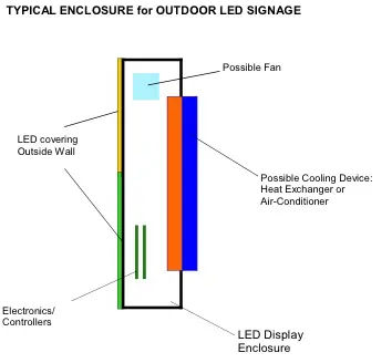
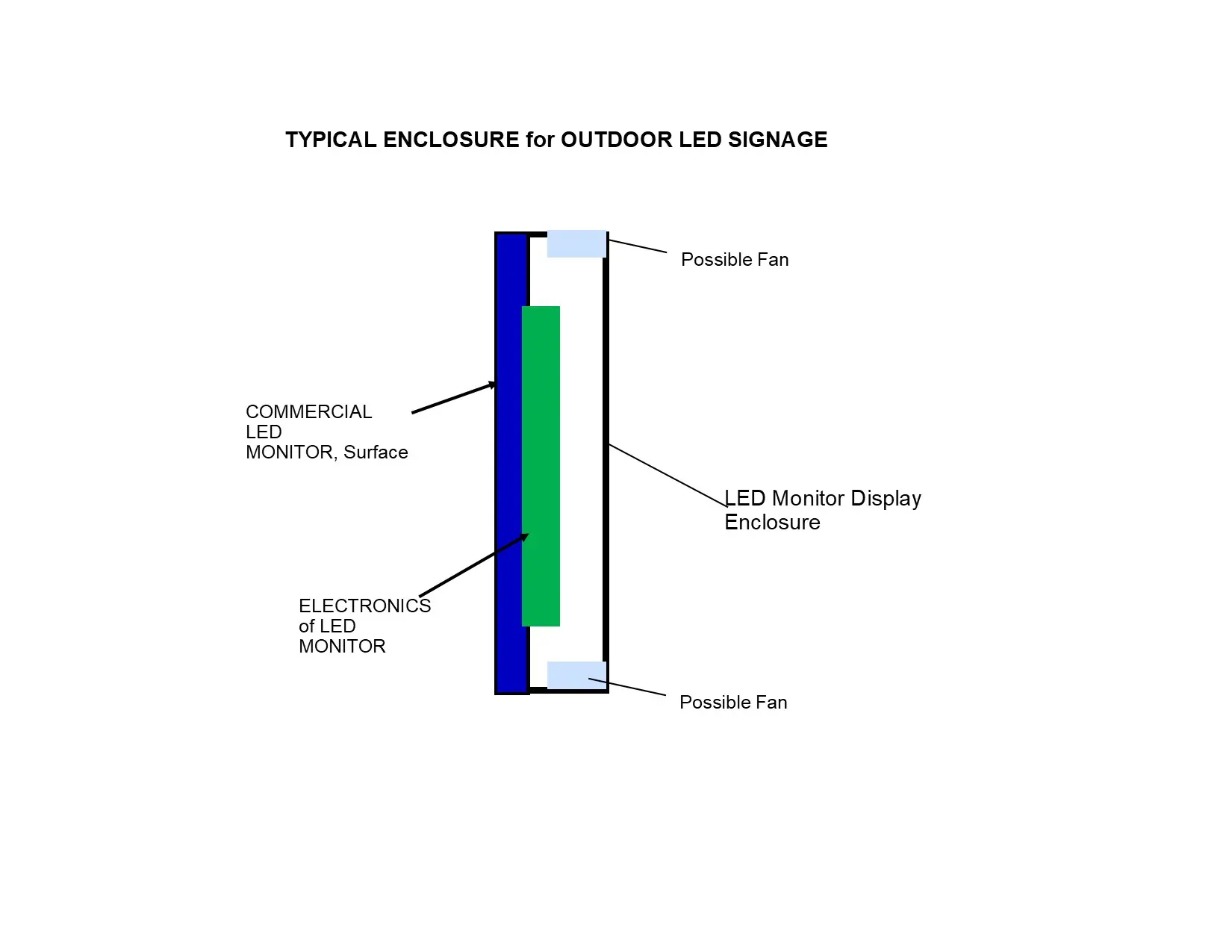
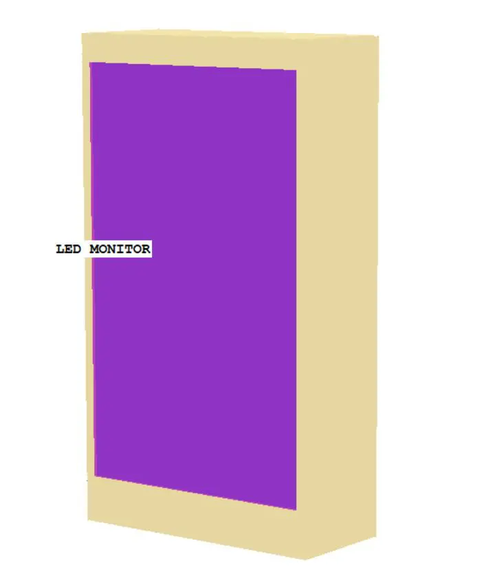
The objective here is to cover the thermal management of LEDs at the system level, both discrete LED modules or outdoor enclosures (LED walls or LED monitors). This assumes that LED and board level thermal management has been dealt with separately. Nowadays, enclosures that contain LEDs are being installed in various environmental conditions. Most will be fitted with either air conditioning/thermoelectric cooling or air-to-air heat exchangers as needed because of relatively high heat dissipation requirements; for lower heat generation levels, flow-through fan cooling is sufficient. For example, there has been an unprecedented growth of the application of LEDs for outdoor (and indoor) signage or video systems such as sports displays, advertising billboards, and gas station pump customer information displays. These all are enclosures with one wall comprised of LEDs. In addition, recently LED display monitors have been installed in outdoor enclosures and therefore require thermal management. Figure 1 shows an illustration of these two types of enclosures.
The goal is to maintain peak temperatures in the enclosures below a certain level that is normally prescribed (the lowest junction temperature of the LED components) by the manufacturers. Humidity levels are of concern, but since most enclosures are either sealed or its temperatures are much higher than the air’s dew points, humidity is generally not a problem (after the transient effect of opening/closing the enclosure is eliminated.)
Figure 1a Typical Enclosure for Outdoor LED Signage Application, The Outer Surface Contains LEDs
Figure 1b Typical Enclosure for Outdoor LED Signage Application, as Found in a Standard LED Commercial Monitor
The designer should be aware that the air temperatures within the enclosures will be a function of: the amount of heat generated by all the electronic equipment in the enclosure; the amount of heat generated by auxiliary and cooling equipment (fans, etc.); ambient conditions (outdoor air), particularly temperature, solar radiation, wind speeds, etc.; objects surrounding the enclosure (shading, ground reflections, buildings, trees, etc.); enclosure design (surface area, shape, paint’s radiation characteristics, etc.) and air exchange with the outside air, either passive by infiltration, or active by fans or blowers.
Typical environmental conditions include ambient temperatures ranging from -40°C to +55°C, for all solar radiation conditions.
Cooling/Heating Load Calculations for Signage/Display Enclosures
Let us consider an enclosure that has installed LED equipment that dissipates a certain amount of heat. The first step is always to realize that the design temperature is that temperature that the enclosure air will attain when there is heat balance, or in equation form:
where, Qequipment comprises the LEDs and its electronics heat dissipation, Qsolar load is the solar heat load and Qcooling-system is the amount of heat removed by the cooling system. The solar load is a complicated term because it includes contributions from all modes or heat transfer. For example:
Normally, the value of Qradiated will always be positive (towards enclosure) but the other two can be either positive or negative, depending on the enclosure’s temperature. Thus, if Qbalance is not zero, this means that the temperature inside the enclosure is either higher/lower than the set temperature and the enclosure is losing/gaining heat by convection and conduction.
Furthermore, since incident solar radiation varies during the daylight hours, the designer must decide whether to conduct a steady state or transient analysis. Moreover, since Qradiation is a very complex term that includes, among other effects, solar declination, latitude, time of year, solar azimuth, atmospheric absorption, atmospheric clearness, re-radiation from other walls, buildings, ground etc., and incident wall surface properties, some simplifying measures must be taken into account. The result is that one can effectively double or triple the amount of heat flux being added into the enclosure depending on the calculation method. The calculation of the cooling load is carried out using several methods. One of these methods is the ASHRAE’s cooling load calculation methods. Normally, when calculating cooling loads, one would include a) Space heat gain, b) Space cooling load, and c) Space heat extraction rate. Space heat gain is the rate at which heat enters or is generated within the space at any given instant. This includes for the enclosure heat transferred into the conditioned space from the external walls and roof due to solar radiation, convection and temperature differential.
One normally includes instantaneous solar radiation effects and delayed effects. The delayed effects include the slow build-up of energy that the external walls accumulate as they absorb solar radiation. This happens because walls are normally thick and massive; making energy absorbed important. For LED enclosures this is not included since its walls are thin (at the most 3 cm when insulation might be added) and should not be included. Another component of heat gain is latent heat due to moisture infiltration. For sealed LED outdoor enclosures, the power electronics are kept in an airtight enclosure with negligible contribution.
One method to calculate the solar load is the Sol-air temperature which involves calculating heat loads using an external temperature that lumps radiation effects and sensible air temperature. No attempt at taking into account solar inclination and radiation intensity variations during a day-cycle is made. One must understand that the enclosure’s solar load is calculated for the worst case condition.
Sol-air Temperature method (see AHSHRAE’s Fenestration Chapter for more details, ASHRAE, 1981, 1986) involves calculating heat loads using an external temperature that lumps radiation effects and sensible air temperature. This is expressed as:
Te = Tout + α It/ho – ε ΔR/ho
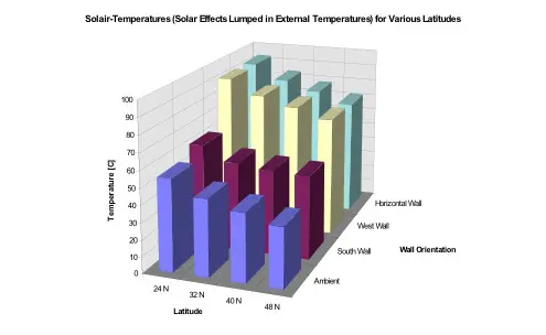
where, α -absorptance of solar radiation surface, It – total solar radiation [W/m2], ho – coefficient of heat by long wave radiation and convection [W/K-m2], ε – hemispherical emittance, and ΔR a radiation correction factor [W/m2]. Figure 2 shows typical Sol-Air temperatures for various latitudes.
Figure 2 Typical Sol-Air temperatures for Various Latitudes.
For roofs: ΔR =63 W/m2, for walls: ΔR = 0, for dark surfaces, α/It = 0.052, which is the maximum value for any surface. To calculate heat transfer into the conditioned space,
Qsolar-load = U A (Te – Tin),
where U is the overall heat transfer coefficient for the wall and A is the surface area for the wall. The term, U, includes convective and radiation effects by the internal and external airflow (See AHSHRAE’s Fenestration Chapter for more details, ASHRAE, 1981, 1986) and the wind outside, in addition to conduction through the walls. The solar load calculated will be added to the equipment load to find the total cooling load. The solar load will include three surfaces that can be illuminated simultaneously, with the roof always included.
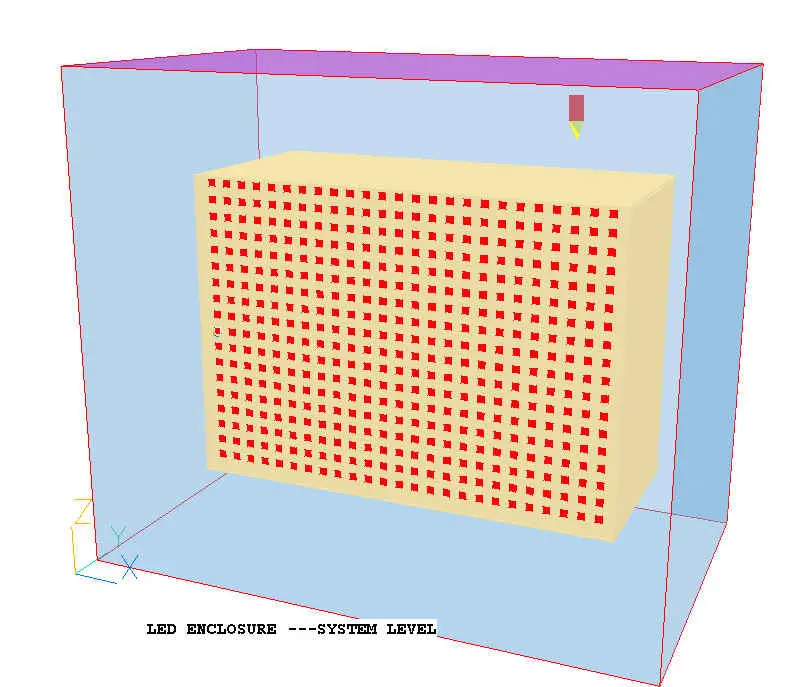
Figure 3 LED Enclosure CFD Phoenics Model (Red Squares are the LEDs.)
Display/signage enclosures have evolved. Typical LED system design has been the display shown in Figure 3. They typically were metal enclosures measuring 5-10 m wide, 250 mm deep and 5 m high. These enclosures could have thousands of LEDs each measuring, typically,5- 8 by 5-8 by 3 mm and dissipating an average of 1W each, all installed on the largest vertical wall. Therefore, the total amount of heat dissipation for this enclosure (including the electronics needed to control and manage the LEDs) could reach thousands of Watts. Figure 3 shows a CFD model of this enclosure using Phoenics by CHAM Ltd of the UK.
Display Enclosures based on Off-the-Shelf LED TV Monitors
In the last few years, display outdoor enclosures are also being designed to house various display signage equipment configurations such as LED monitors with dissipating heat rates ranging from 200 to 1500 W, depending on the size and type of auxiliary equipment. These enclosures are installed in various environmental conditions, and typically the enclosures, without major structural modifications, may be fitted with fans, air conditioning or air-to-air heat exchangers as needed. Figure 4 shows at typical enclosure (CFD model).
Figure 4 Illustration of an outdoor digital media system enclosure (CFD Model)
Equipment housed in these enclosures include TV LED monitors that have been initially designed for indoor use and have been slightly hardened to be placed in a hot, dry environment without the support of an enclosure. Many manufacturers sell these monitors.
For example, here are typical environmental specifications of a semi-outdoor LED monitor Samsung (OMD-W Series 75″):
Environmental Conditions
Operating Temperature
0℃~ 30℃ (Direct Sunlight)
0℃~ 50℃ (w/o Direct Sunlight)
0℃~ 50℃ (Direct Sunlight in Cooling System)
Operating Humidity
10~80%
The goal of the designer is to maintain the peak temperatures in the enclosures, which are below a certain level that is normally prescribed by the electronic equipment manufacturer. Humidity levels are also of concern, but since in most enclosures, its temperatures are much higher than the air’s dew points, humidity is generally not an issue (after the transient effect of opening and closing the enclosure is eliminated). However, typically, the LED monitors are not fully outdoor rated, that is they must be protected from rain and moisture, therefore they must be installed in IP55/56/66 enclosures.
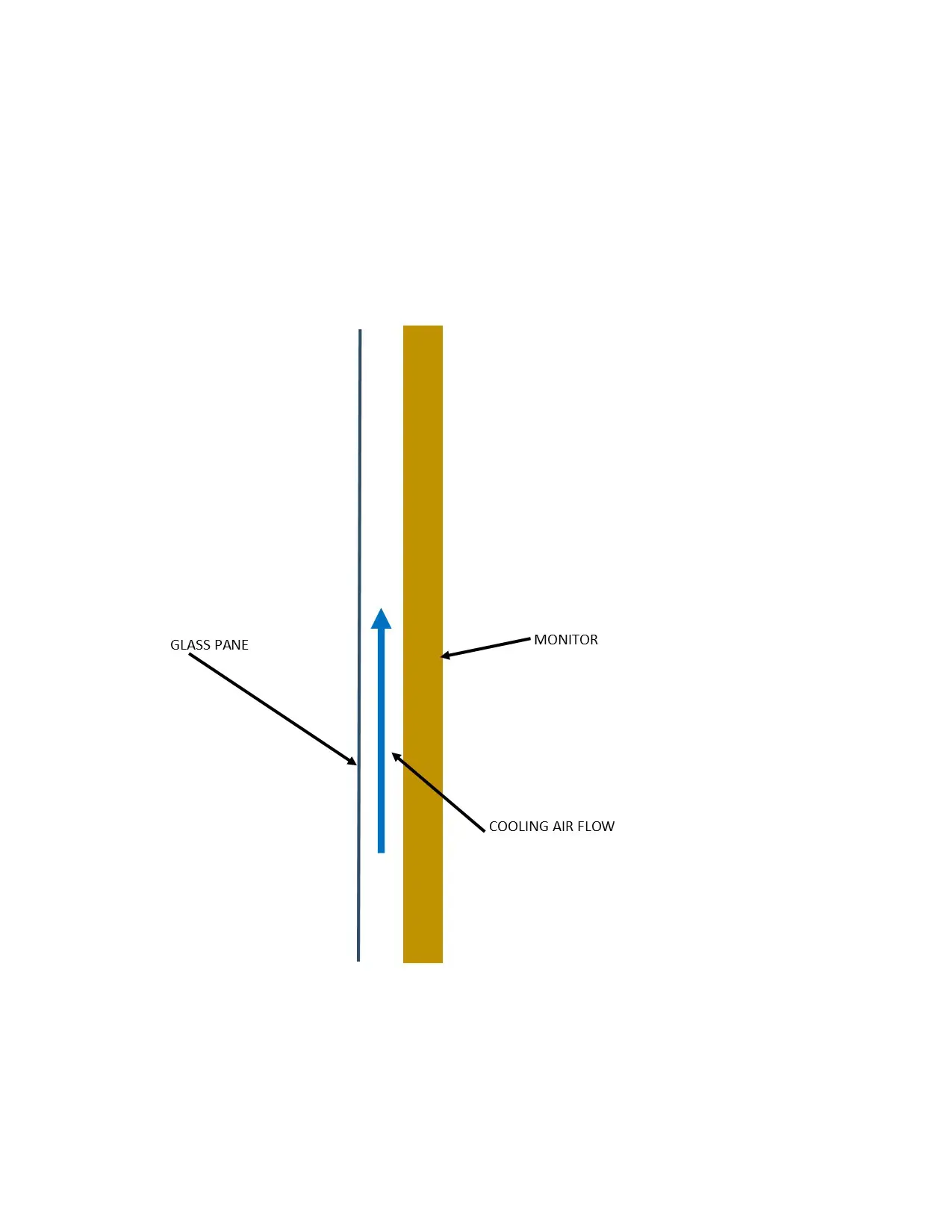
Most enclosures need to be designed to keep the system operating with slight internal overpressure. Cooling air is guided to flow into a gap between the LED screen surface and external transparent wall guided by guide-vanes, and the cooling system also must allow for air to flow to the rest of the enclosure, in addition to the flow in the LED/Wall gap. Overpressure is used to maintaining IP55 and IP66 design and a fan and filter inlet system construction allows for proper solar mitigation technology. For further solar mitigation purposes, if used, a solar shield overhang can reduce solar loading.
Finally, of paramount importance is to keep the LED surface (especially when in full solar exposure) under a maximum temperature. For the above LED monitor, this temperature is 110 C. Since, maximum solar radiation for latitudes below 35 N or S can generate surface temperatures higher than 110 C, then a typical construction would involve a gap between the outdoor facing glass plane and the LED monitor (see Figure 5).
Figure 5 Details of a Monitor Surface Cooling Design
