BY: Lauren Boston, Andrew Yu, Timothy Chainer, Edward Yarmchuk, and Michael Gayness
To improve cooling of electronic components, a heat spreader is typically attached to the component to spread the heat laterally and facilitate the heat removal by a heat sink. To ensure good thermal conduction between the heat spreader and heatsink, a thermal interface material is applied between the mating surfaces. During operation, changes in temperature of the electronic components, heat spreaders, heat sinks and circuit board result in thermal expansion which places stress on the thermal interfaces. Therefore, to ensure a reliable thermal solution, it is important to quantify the mechanical stability of the thermal interfaces. In many cases, the thermal interface material is non-conductive (electrically) with a dielectric constant which can be easily measured. This allows electrical capacitance to be used to monitor the thermal mechanical stability of thermal interface materials (TIMs) between a component heat spreader and heat sink. The component heat spreader and the heat sink provide parallel plates of a capacitor with the TIM in between as the dielectric. The measurement of capacitance is straightforward, fast and accurate (+/-0.08%) [1, 2].
CAPACITANCE AND THERMAL RESISTANCE CORRELATE
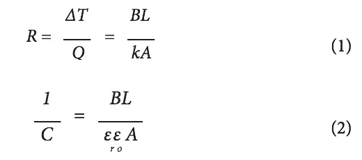
As shown in Equations (1) and (2), thermal resistance (R) and the inverse of electrical capacitance (1/C) have the same geometric dependence on TIM bond line (BL) and area (A). In equation (1), the thermal resistance R (given by temperature gradient ΔT divided by the heat conduction rate Q) is equal to the TIM bond line (BL) divided by the thermal conductivity (k) and area (A). In equation (2), the inverse electrical capacitance (C) is equal to the TIM bond line (BL) divided by the permittivity of free space (εo), the relative dielectric constant (εr) and area (A). Therefore, the electrical capacitance between the component heat spreader and either the chip within the component or an external heat sink can provide a direct probe of the bond line thickness and material integrity of the dielectric TIM.
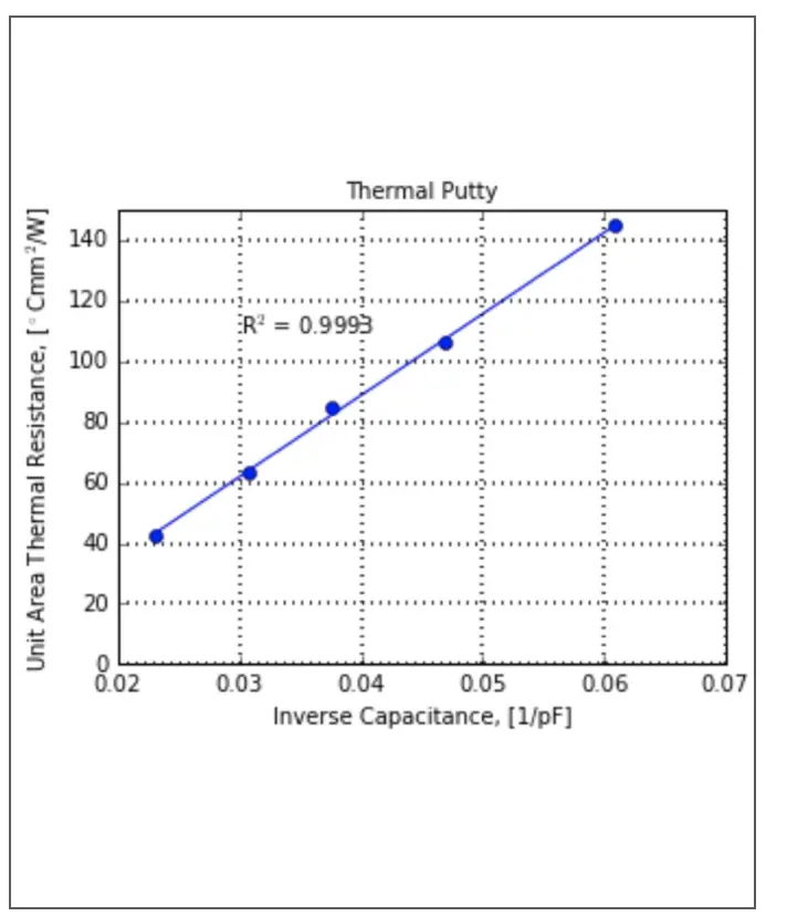
To demonstrate the correlation between capacitance and thermal resistance, samples were made of two 12.7 mm diameter aluminum rods of length 50 mm aligned end-to-end in a V- block with TIM in between. The bond line of the TIM was measured with a micrometer and the capacitance was also measured. Next, thermal resistance was measured in a thermal rod test apparatus previously described [3]. Figure 1 shows the plot of unit area thermal resistance vs inverse capacitance with excellent correlation.
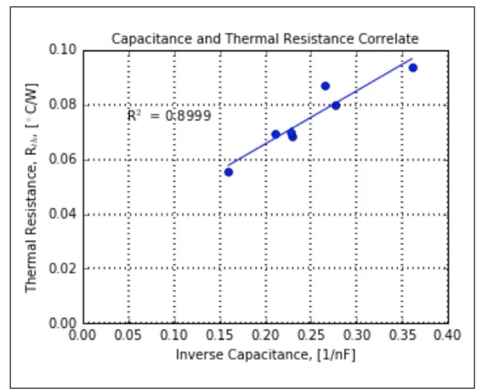
In commercial integrated circuit packages, the chip and heat spreader thermal conductivities are typically much higher than that of the TIM, but not infinite, so lateral gradients can be significant and the analogy to the electrical situation will be imperfect. Therefore, capacitance cannot be used as a substitute for detailed thermal modeling and measurement of packages. However, overall heat spreader to chip capacitance does reflect the average thermal conductance of the TIM and will track variations in thermal performance of parts. Figure 2 illustrates this for a group of Flip Chip Plastic Ball Grid Array (FCPBGA) thermal test modules where capacitance and thermal resistance were measured. The capacitor plates in this measurement were the copper heat spreader and the silicon thermal test chip. The FCPBGA modules were solder attached to printed circuit cards. Probing the copper heat spreader was direct. The chip was accessed by probing the card connections to the chip heaters that were connected together. Included in the capacitance measurement are the series capacitance from the dielectric layer in the chip that separates the chip circuitry from the bulk silicon, and the parallel stray capacitance between the heat spreader and the substrate wiring. Both of these vary < 5% part to part and can be measured separately to be subtracted from the total capacitance measured, if desired. As Figure 2 shows, there is good correlation between thermal resistance and inverse capacitance. Thus, capacitance provides a very simple means of tracking overall thermal performance among groups of parts.
Figure 1: Plot of unit area thermal resistance vs inverse capacitance measured on aluminum rod samples.
Figure 2: Plot of thermal resistance vs inverse capacitance measured on thermal test FCPBGA modules attached to cards.
When printed circuit board (PCB) assemblies with TIMs are subjected to environmental stress tests such as thermal cycling, damage can occur in the TIM. The damage can include pump-out, voiding, cracking, delamination and fracture which all result in a change of capacitance. In this damaged state, the TIM is not uniform in either thermal conductivity or dielectric constant. In the case where the damaged TIM has regions that are continuous from one interface to the other and is interspersed with missing material due to voids, cracks or pump out, the change in capacitance will be a good indicator for the change in thermal resistance as shown in Figure 2. The measured capacitance of the damaged TIM can be used with the dielectric constant to calculate a new capacitance bond line for comparison to the starting undamaged capacitance bond line. The percent increase in capacitance bond line is a good indicator for an expected increase in thermal resistance. It is important to emphasize that the bond line has not actually changed, rather the TIM within the bond line has changed due to the presence of air (missing TIM). The dielectric constant has changed to a composite of the TIM and air dielectric constants. Similarly, the thermal conductivity in the damaged TIM is a composite of the TIM and air thermal conductivities which is expected to result in similar fractional changes in both inverse capacitance and thermal resistance.
If the TIM were to delaminate from one interface or fracture, the thermal resistance change would be much higher than the capacitance change. In a split geometry with an air layer and a TIM layer, the effect of the air layer is much larger for thermal resistance than it is for capacitance because the TIM and air thermal conductivity ratio (~230) is much greater than the dielectric constant ratio (~10). Therefore, the capacitance bond line should not be used to quantify a percent increase in thermal resistance. An indication of delamination or fracture in the capacitance curve should appear as a sudden decrease, similar to the sudden drop in load for mechanical strength testing that is characteristic of fracture. Careful visual inspection of the TIM after separating the heat sink from the component at the end of testing should show predominantly planar fracture surfaces with little to no evidence of cracks or pump-out.
USING CAPACITANCE AS AN INDICATOR FOR THERMAL RESISTANCE ON MECHANICALLY REPRESENTATIVE HARDWARE
Many TIMs are low molecular weight organic polymers with no cross-linking, such as thermal greases and phase change materials, or with light cross-linking such as putties, gels, and pads. The organic polymer is also highly filled with thermally conductive fillers. While compliance is a desired property in TIMs, if too high (as in a grease) results in material movement during thermal cycling. As filler content increases to achieve lower thermal resistance, compliance decreases. Too little compliance allows thermal mechanical stresses to build that can result in fatigue failure that includes fracture and delamination. Material responses such as long term adhesion and cyclical thermal mechanical loading require experimental study, especially if environmental aging and cyclic loading have cumulative damage effects. To understand material changes over a design lifetime and to enable effective virtual qualification, physical experiments are needed during the early design phase [4].
Previously, electrical capacitance was used to monitor the stability of TIMs using product development hardware that was designed, procured and assembled, taking several months [5]. A more recent study used a blank FR4 board, component heat spreaders and a large aluminum plate as a common heat sink. All parts were procured in less than two weeks [3]. Component heat spreaders were bonded on the FR4 board. Thermal interface materials of interest were dispensed on every component heat spreader and interfaced to the aluminum common heat sink. This mechanically representative design took only weeks to assemble compared to months to obtain early development hardware. Therefore, this new approach can provide an early evaluation of the thermal and mechanical design to either identify problems or confirm an acceptable design.
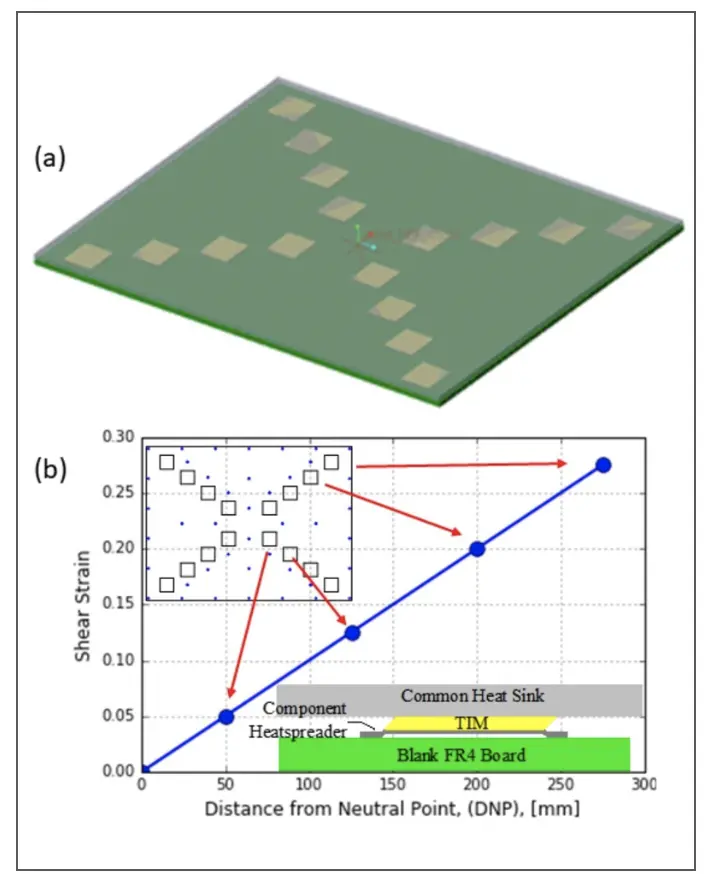
Figure 3 (a) shows an isometric view of the blank FR4 board, 440Î590Î6.4 mm, representative in size of many commercial applications. Depicted along the diagonals are the locations for the component heat spreaders, typically used on processor and ASIC modules. The heat spreaders were bonded with a room temperature curing structural adhesive to the FR4 board along the diagonals at distances from the center neutral point (DNP) of 50, 125, 200 and 275 mm. The aluminum common heat spreader, 440Î590Î6.4 mm, was thermally interfaced to the component heat spreaders and fastened to the FR4 board at locations depict- ed by the blue dots in Figure 3 (b). A spacer was located at every screw location and used to define a fixed bond line between the FR4 board and common aluminum heat sink that resulted in a design bond line of 0.5 mm. The resulting shear strains in the TIM at 100 ºC, the peak temperature during thermal cycle testing, were 0.05, 0.13, 0.2 and 0.27.
Figure 3. (a) Isometric view of the FR4 board and component heat spreader positions along the diagonals. (b) Plan view of FR4 board with heat spreader positions as open squares and screw locations as blue dots with plot of shear strain in the TIM vs. DNP on the FR4 board.
RESULTS AND DISCUSSION
During the thermal cycle between 0 and 100ºC, the capacitance increased with temperature from 25ºC to 100ºC, indicating that the TIM was being compressed. The capacitance decreased during the cold portion of the thermal cycle at 0ºC, indicating that the TIM was being pulled in tension [3].
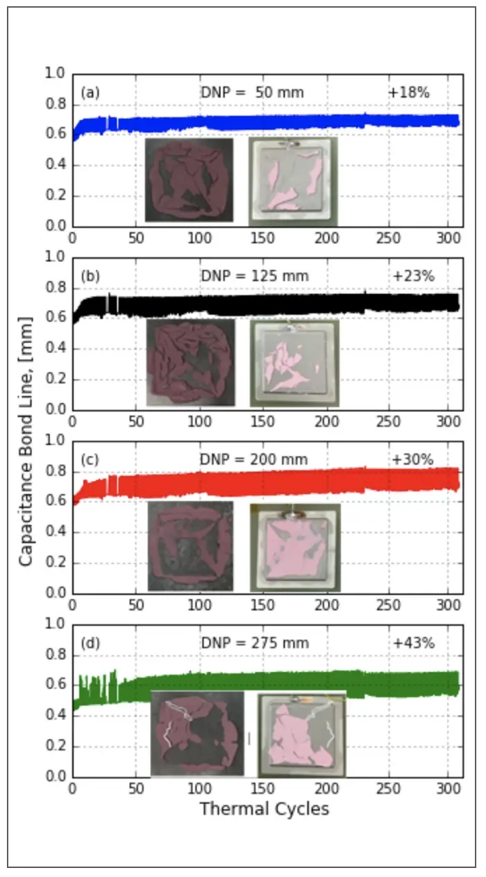
The thermal cycle test results for a thermal putty, TIM A, appear in Figure 4, which includes a plot of the capacitance bond line vs. thermal cycles and photos of the TIM after the aluminum common heat sink was separated from the component heat spreaders. As discussed in Section 2, with damage to the TIM, the dielectric constant is a composite of the TIM and air dielectric constants. However, to quantify the impact of the change in capacitance, we use the TIM dielectric constant to calculate a new capacitance bond line that is different from the initial bond line, understanding that the physical bond line has not actually changed. The photos in Figure 4 clearly show damage in the TIM in the form of voids and cracks caused by TIM movement during the test. The plots in Figure 4 also show the capacitance baseline bond line increasing with cycles with greater peak to valley changes as the DNP increases.
Figure 4. Thermal putty TIM A capacitance bond line plots and photos after separation. Left photo is the common aluminum heat sink and the right photo is the component heat spreader.
The initial capacitance bond line for Figure 4 (a) was 0.61 mm and the reduction in capacitance during the first 25 thermal cy- cles is equivalent to a bond line that increased to 0.67 mm (10%), indicating that structural change had occurred in the TIM. Between cycles 25 and 300, the continued decrease in capacitance is equivalent to a further increase in bond line from 0.67 mm to 0.72 mm for a total increase of 18%. The heat spreaders at the higher DNPs experienced higher increases in the capacitance bond lines of 23%, 30% and 43%, respectively in Figure 4 (b), (c) and (d), consistent with the expectation that increasing strain will accumulate more damage in the TIM.
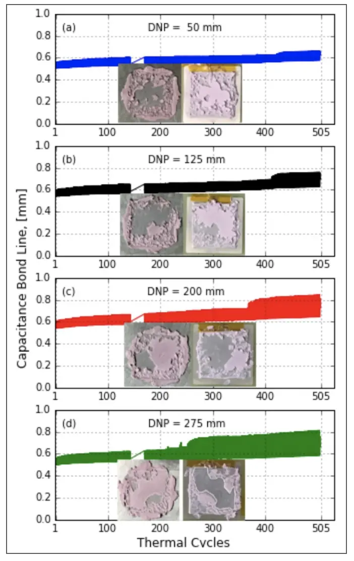
Figure 5. Thermal putty TIM B capacitance bond line plots and photos after separation. Left photo is the common aluminum heat sink and the right photo is the component heat spreader.
The photos in the plots show the separated TIM surfaces presented in an opened book manner. In Figure 4 (d), white tracing is used to highlight where TIM is missing on both the heat sink and the heat spreader surfaces. Careful study of the photos reveals that similar cracks in the TIM exist at all heat spreader locations on the FR4. The presence of cracks and voids results in the thermal conductivity being a composite of the TIM and air thermal conductivities, lowering the average thermal conductivity in the bond line and indicating an accompanying increase in the bond line thermal resistance.
The thermal cycle test results for a second thermal putty, TIM B, appear in Figure 5. Evident in all four plots is a sudden increase in the capacitance bond line (sudden decrease in capacitance) that appears at ~250 thermal cycles at the highest DNP and progressively later to ~425 cycles at the lowest DNP. Inspection of the TIM surfaces after disassembly shows large areas as indicated by the white tracing in Figure 5 (d) that appear to be delamination of the TIM near the interface of either the aluminum or component heat spreader. This observation is consistent with the sudden increase in capacitance bond line as delamination results in a sudden drop in capacitance. As previously described in Section 2, when delamination of the TIM occurs the capacitance bond line should not be used to quantify a percent increase in TIM thermal resistance since the thermal resistance change would be much higher than the capacitance bond line change. More importantly, the results demonstrate that TIM B is very susceptible to thermal mechanical breakdown and should not be used in applications exposed to thermal cycling shear strains that exceed 0.05.
CONCLUSIONS
Electrical capacitance is an effective indicator for thermal resistance characterization. Mechanically representative hardware is simple, fast and inexpensive to procure, very early in a development program compared to the long lead time and expense to design, procure and assemble early production, thermally testable hardware. TIM candidates can be ranked and the effectiveness of a thermal solution can be assessed. Early discovery of deficiencies allows time for material, design and process changes.
ACKNOWLEDGMENTS
Dr. James Wilcox, Area Array Consortium, Universal Instruments Corporation and Prof. David Klotzkin, Binghamton University, for their guidance and support of this Senior Engineering Project at Binghamton University.
REFERENCES
- Gaynes, M. A. and Yarmchuk, J., “Process for Measuring Bond Line Thickness,” US Patent 776409B2, Jul. 27, 2010.
- Chainer, C., Gaynes, M. A. and Yarmchuk, E. J., “Using In situ Capacitance Measurements to Monitor the Stability of Interface Materials in Complex PCB Assemblies and Other Structures,” US Patent 8589102B2, Nov. 19, 2013.
- Boston, , Yu, A., and Gaynes, M., “Using Electrical Capacitance and Mechanically Representative Hardware to Monitor the Thermal Mechanical Stability of Thermal Interface Materials”, SemiTherm 34, San Jose, CA, March 2018.
- Doman, J., Kobeda, E., Bielick, J., Kuczynski, J., Tofli, and Vaughn, M., “Evaluation of Thermal Interface Material Performance in a Cyclic Strain Environment”, Proceedings of the Surface Mount Technology Association, International (SMTAi) Conference, Florida, October 24-28, 2010.
- Gaynes, M., Chainer, , Yarmchuk, E., Torok, J., Edwards, D., Olson, D. and Pizzolato, K., “Using In situ Capacitance Measurements to Monitor the Stability of Thermal Interface Materials in Complex PCB Assemblies”, IMAPS Conference, Raleigh, NC, 43rd International Symposium on Microelectronics, pp. 450-457, November, 2010.

