Introduction
Electronics thermal management has become an increasingly important design focus as devices have become more constrained, more powerful, more expensive and more ubiquitous. To manage temperatures, particularly in mobile devices, thermal engineers typically use higher thermal conductivity components and materials. Electrical engineers strive to spatially distribute the higher power components, and also to throttle workloads to manage the peak temperatures. Latent heat storage materials (LHS materials), sometimes referred to as phase change materials (PCMs), can be useful in reducing the temperature peaks during periods of high compute and communication workloads, and thus, reduces the demands placed on the thermal conduction and power throttling capabilities of the device.
Since PCMs typically have a low thermal conductivity, they are normally integrated with a second, higher–thermal–conductivity material to optimize their performance in an application. This is usually accomplished by mixing higher conductivity particles in a matrix consisting of the PCM. However, the low value of the effective thermal conductivity of the resultant composite material, ~1 W/m-K, requires that all the PCM material be located directly in the heat flow path from the heated component to the heat sink. In order to get sufficient mass of PCM to absorb the required amount of heat during the power transients, it is normally necessary to have a thickness of several millimeters. [1] Thicknesses of this magnitude have been successfully integrated into larger mobile devices, such as tablets. However, they are too thick to be integrated into the thin-form-factor smartphones of today.
By applying the PCMs as a solid coating on a high–thermal–conductivity substrate (k > 150W/m-K) the PCM can extend beyond the heat flow path and achieve the required volume of PCM, but at a smaller thickness than with a more conventional PCM. High-thermal-conductivity materials such as copper, graphite, and AlN have been successfully used as substrates for PCM coatings. The solid coating is a combination of polyacrylic matrix with highly dispersed microencapsulated PCM regions. This article evaluates PCM-coated copper substrates fabricated at a total thickness of 1 mm or less.
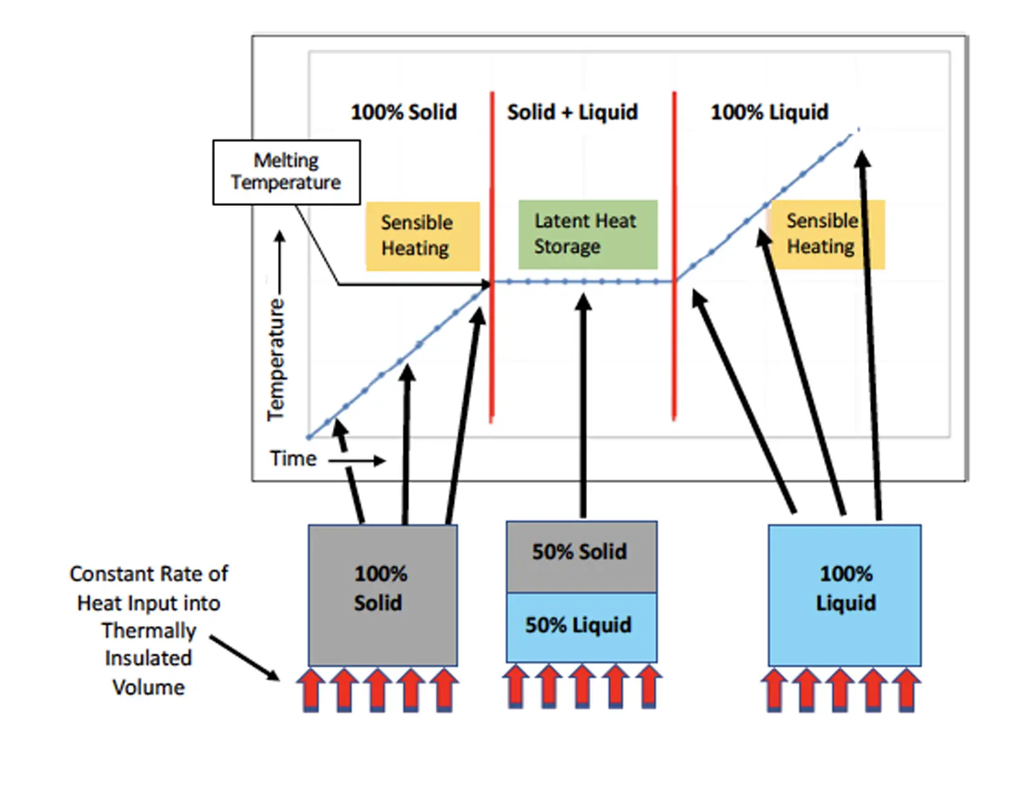
The Phase Change Process
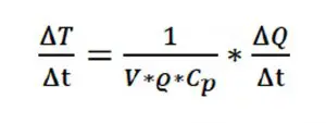
where, ∆T/∆t = °C/sec, V = Volume (cm3), [Equation] = mass density (g/cm3), [Equation]p = specific heat at constant pressure (J/g/K), ∆Q/∆t = [Equation]= J/sec = Watt.
Once the melting temperature, TMelt, has been reached at the end of stage 1, the PCM begins to liquify, and becomes 100% liquid at the end of stage 2. The temperature remains equal to TMelt throughout stage 2. Any thermal energy flowing at a constant rate into the PCM melts the PCM at a rate determined by Eqn. 2:
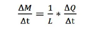
where M = mass (g) of liquid PCM, and L = specific latent heat of fusion (J/g). Clearly, the greater the total mass of PCM, the longer it would take to melt the PCM at a specified rate of heat generation.
The amount of heat required to heat up the sample from an initial temperature T1, which is lower than the melting temperature, and then melts all of the material is:
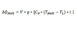
The time required to complete the above process equals ∆QMelt (determined by Eqn. 3) divided by the power:
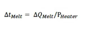
The above analysis, indicates that, once the temperature of the PCM reaches the melting temperature, TMelt, this melting process serves to moderate temperature increases in a component in thermal contact with it. However, once the PCM is entirely liquid, its ability to moderate temperature increases in the component ceases, apart from the relatively small energy absorption associated with its specific heat. Hence, in the application of PCMs, it is important to have an estimate of how long it would take for the PCM to become entirely liquified so that this condition could be avoided as much as possible in the application.
In actual applications, the PCM is not thermally isolated, but, rather, it is configured to transfer heat to the ambient to extend the time before the PCM completely melts. Hence, the value of ∆TMelt determined by the above procedure for a thermally isolated PCM would represent a lower bound compared with the typical situation in which heat is lost to the ambient. Nevertheless, despite its approximate nature, the above calculation has value because of its simplicity.
PCM Combined with Copper Sheet and Foil
Experimental Method:
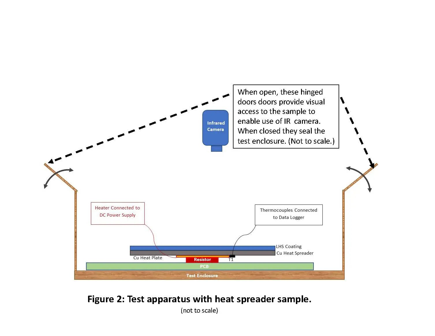
A test apparatus thermal kit (Figure 2) was designed using a 2–W, 4–ohm wire–wound resistor (5 mm X 10 mm) attached to an isolated FR-4 PCB (7.2cm X 9.5cm) placed in a controlled-environment sealed container (14.5 cm X 14.5 cm X 16.5 cm) and centrally positioned. A small 10 mm x 10 mm copper plate of 550 µm thickness was attached to the resistor using a thermally conductive epoxy adhesive. A thin thermocouple was attached to the side of this small plate as the embedded thermocouple. A regulated DC power supply [2] operating at 3.0 V and 0.78 A produced a constant power output of 2.4 W. Heat spreader samples were attached to the heating element using small amount of thermal compound [3] and were approximately 8 mm above the PCB. These temperatures were presumed to be more indicative of the effect that materials would have on a realistic heating point, i.e. CPU, resistors, etc.
Figure 2. Test apparatus with heat spreader sample
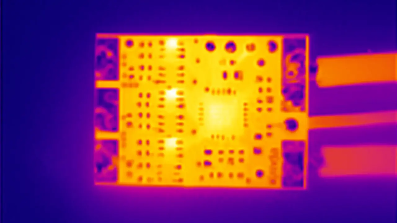
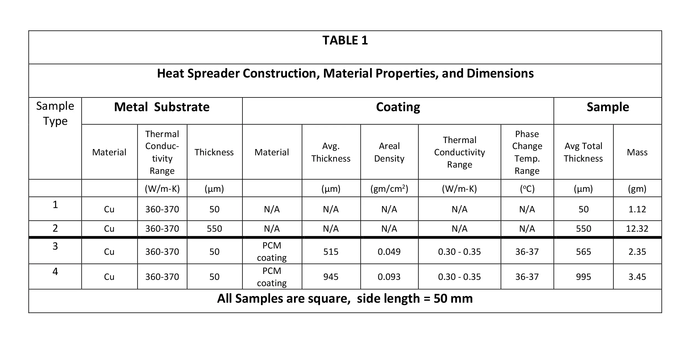
Thermal images were obtained with a commercial infrared (IR) camera [4] immediately after opening the enclosure by the IR camera positioned over the enclosure. The various experimental samples are described in Table 1, which provides details of the sample construction, the material properties, and critical dimensions.
Copper foil and sheet heat spreaders were made of 99+% pure material. The coating was a combination of polyacrylic matrix with microencapsulated C20 (Eicosane) PCM. The PCM had a phase change temperature of 36-37oC. The polymer matrix encapsulated the PCM and mitigated the effects of bulk volume changes of the PCM during its solid-liquid phase transition. The LHS coating had a specific latent heat of fusion of 120-130 J/g and a specific heat of 2.1-2.2 J/g·K.
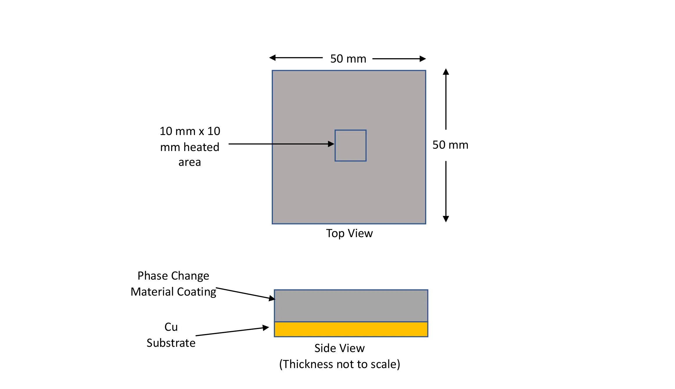
The experimental setup was designed under the assumption that the energy source to be cooled has an area of contact significantly less than the overall surface area of the heat spreader. Thus, by taking advantage of the available volume in the device beyond the component to be cooled, a much greater volume of PCM can be put in thermal contact with the energy source while keeping the overall thickness of the PCM coated heat spreader less than or around 1 mm.
Figure 3 depicts the design concept for the samples evaluated here. It consists of coating a copper substrate with a PCM coating layer of a solid form of the PCM.
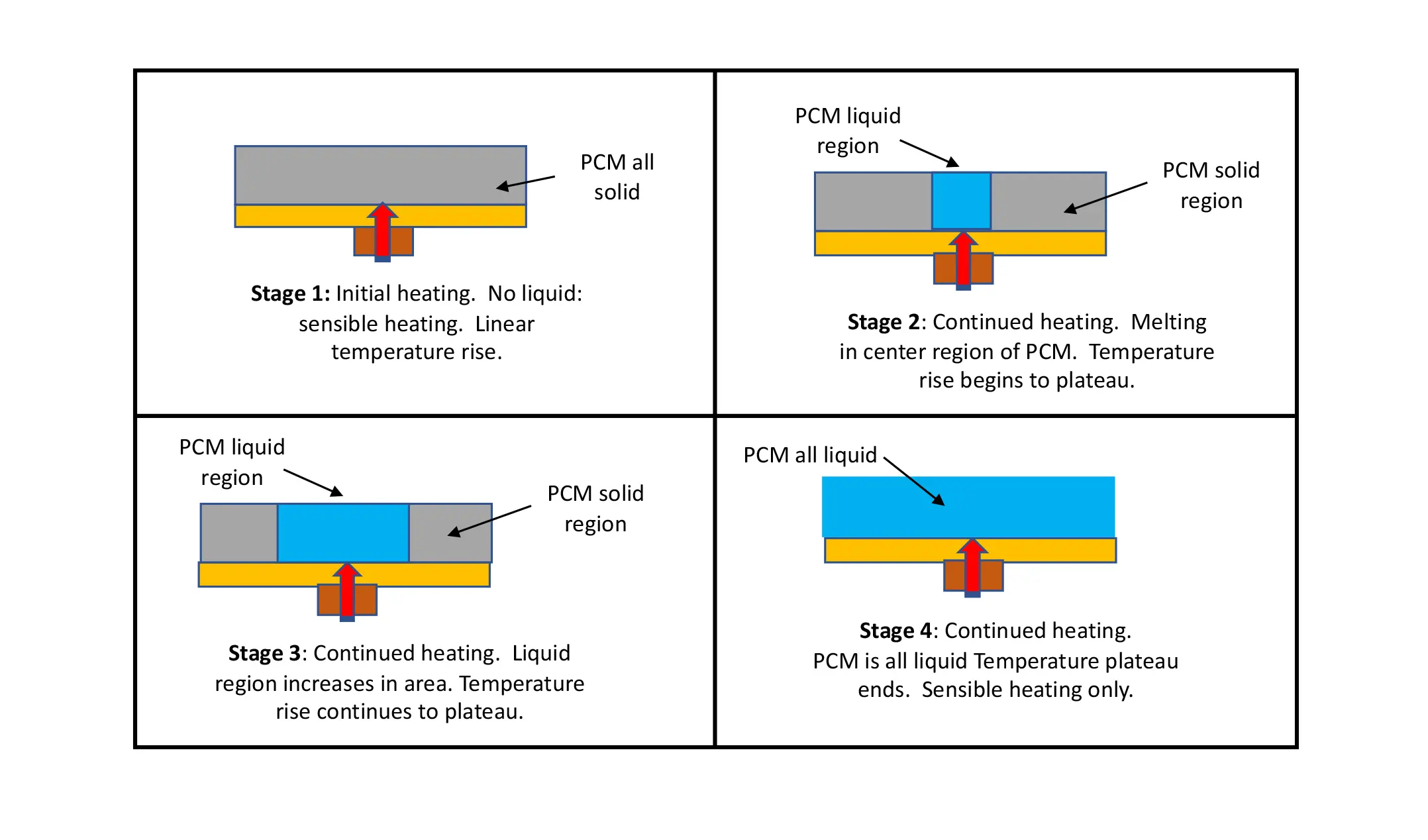
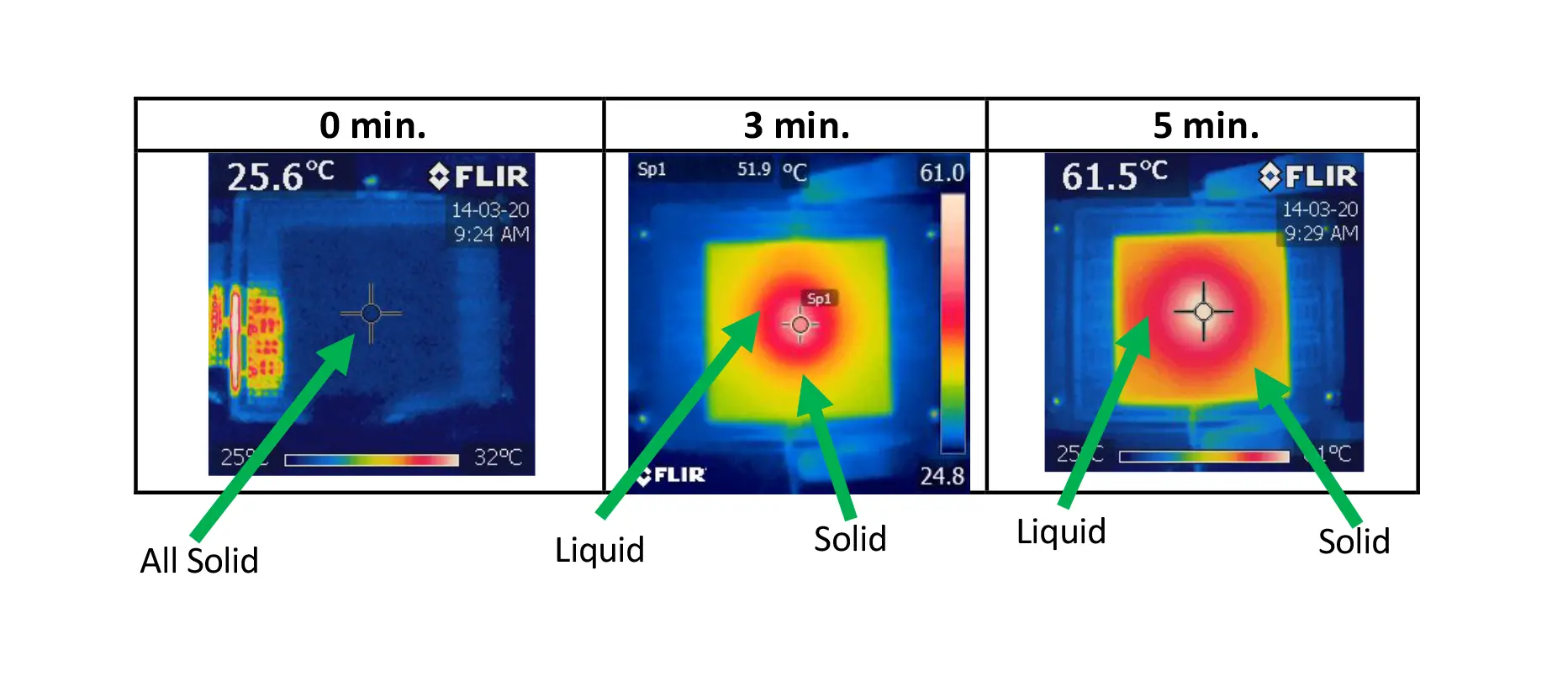
Figure 4. Depicts the different stages of the phase change in a solid coating on a heat spreader with a centrally located heat source much smaller in extent than the substrate. The molten region of the PCM is initially created in the center. Over time, it spreads radially until the PCM everywhere in the sample becomes molten. The IR images in Figure 5 illustrate this process vividly and show clearly the radial spreading of the molten region of the PCM.
Figure 4 depicts the different stages of the phase change in a solid coating on a heat spreader with a centrally located heat source much smaller in extent than the substrate. One notes that the solid-liquid interface travels radially outward from the heated region in the center of the sample. The IR images in Figure 5 illustrate this process quantitively by virtue of the fact that the liquid phase exists in a narrow temperature range and, hence, appears as an isothermal region, in this case, identified by a red color in the image. Also, one should keep these 4 phases in mind when interpreting the temperature profiles in Figure 6.
Figure 5, IR Images—Sample 3. 50 μm Cu foil with 565 μm avg. thickness PCM coating. Measured at 2.4W constant power input. Due to the small melting range (36-37°C) the liquid region of the PCM appears to be isothermal and is colored red. This behavior should be compared with the temperature profile for this sample in Figure 6.
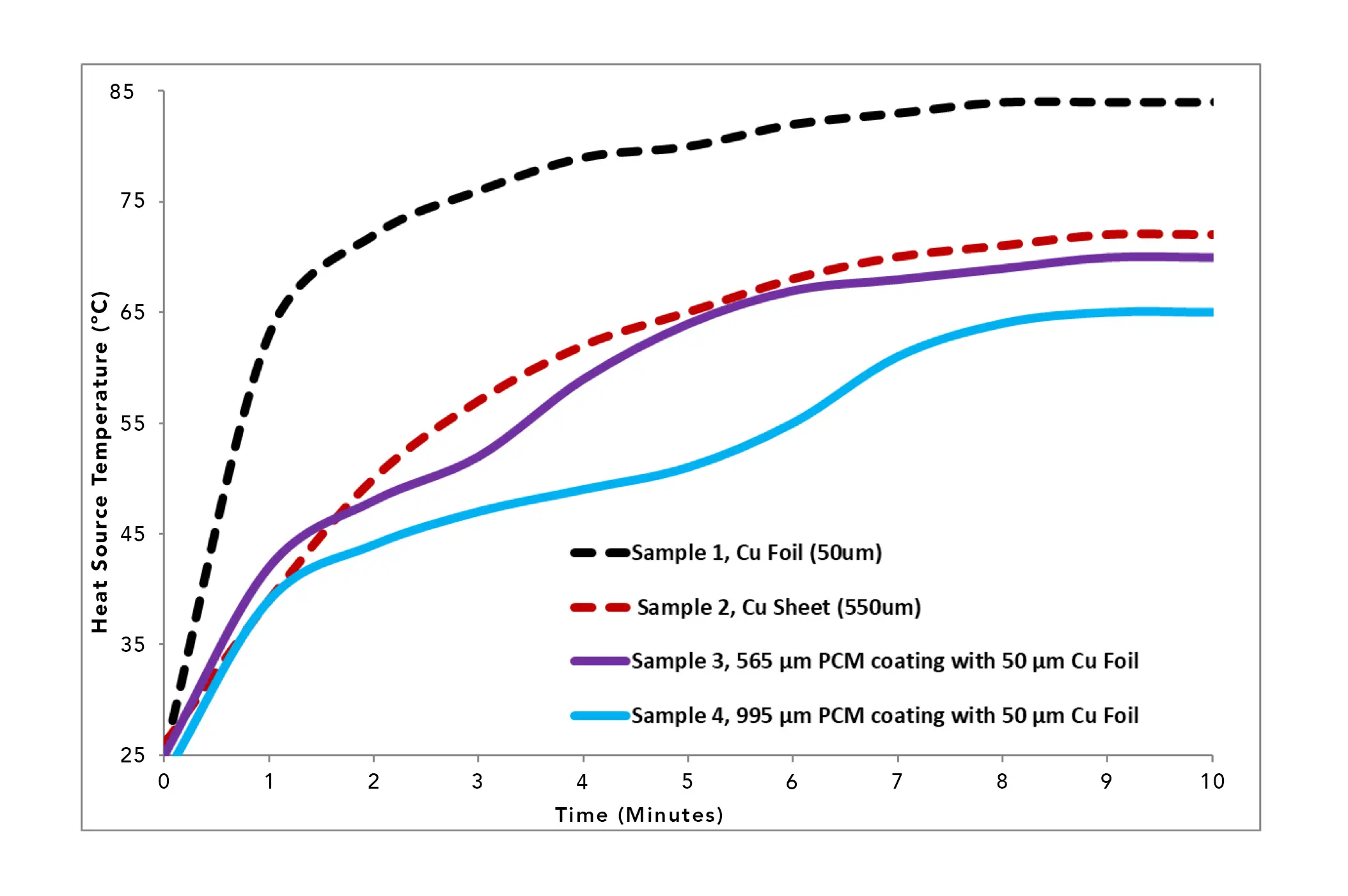
Figure 6. Temperature Profiles for uncoated and PCM coated copper heat spreaders, Samples 1 – 4. Conditions: 2.4W constant power for 10 minutes. Ambient temperature = 25°C.
Discussion
Figure 6 shows the temperature profiles of the two copper heat spreader control samples and two PCM-coated samples. These four samples were evaluated to show the variables of a) improved thermal conductance of thicker copper (50 µm copper foil versus 550 µm copper sheet), and b) temperature delay/plateauing benefits of a PCM coating on a copper heat spreader, due to the effect of latent heat thermal energy storage.
The standard copper materials (Samples 1 and 2), without any PCM, performed as expected, where the samples exhibit monotonically increasing temperatures, as is typical for a sensible heating process. There are no phase transitions that would result in plateaus in the heating curve. The copper foil, which has the least mass, had the fastest rate of temperature increase and the highest steady-state temperature, the result of having a lower heat spreading ability. The thicker, higher mass 550 µm copper sheet, had lower rate of temperature increase due to its higher mass and a slightly lower steady-state temperature (84oC versus 72oC), due to its greater heat spreading ability.
The temperature profiles for Samples 3 and 4 show the temperature curves of the 2 coated–copper–foil samples. These two coated samples are interesting in that when additional material was added to the 50 µm copper foil, they perform comparably or better than the thicker, higher–mass copper 550 µm sheet, by exhibiting a reduced temperature during the transient stage and a delay in reaching the steady-state stage.
As the materials approach the 10-minute time, the phase change in Sample 3 is mainly complete and is slowly approaching steady state. Sample 4, due to its higher mass of PCM and associated total latent heat, is not completely phase changed and yields lower temperatures, further delaying full steady state conditions.
It is worth comparing the values of ∆tMelt calculated for Samples 3 and 4 using Equations 3 and 4, assuming thermally isolated PCMs, and values of Ti and Tmelt equal to 25°C and 36.5°C, respectively. The results are: Sample 3,761 sec (12.7 min) and Sample 4, 1,444 sec (24.1 min.) These calculations are consistent with the observed time/temperature behavior. Sample 3 appeared to be approaching steady state at the 10 minute mark. On the other hand, at this same value of elapsed time according to the calculations, in Sample 4 less than half of the PCM had undergone a phase transition into the liquid state. These results demonstrate the utility of these simple calculations in providing a lower–bound estimate for how long it will take for a given PCM to completely liquify.
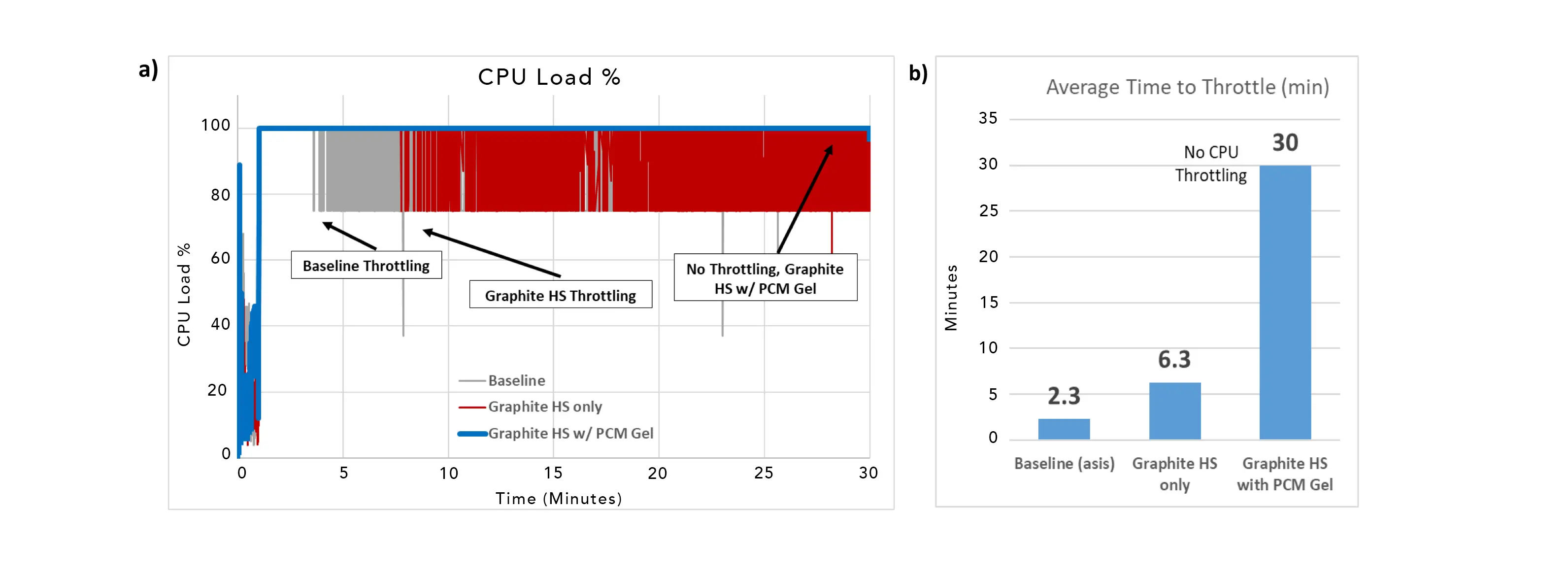
Therefore, PCMs provide their optimum benefits in applications with transient power loads where the PCM and heat spreader are optimized for the application requirements and device design. This can include adjusting PCM phase change temperature, amount, placement in the device along with varying heat spreader material and size. Continuing this concept, various configurations of heat spreaders and PCMs were tested in a commerical tablet device. Figures 7a and 7b show the average time to CPU throttling and the CPU load percent in a tablet when optimized systems are utilized. The tablet was analyzed for 30 minutes under Dhrystone [5] conditions with a 25 µm graphite heat spreader combined with a 1 mm PCM gel. The PCM heat spreader was positioned between the electronics and back cover with graphite heat spreader side covering the full area of the electronics (10.5 cm X 15.3 cm). These results show that for a 30–minute run time, the device with the PCM heat spreader experienced no throttling at all. In comparison, the table with no heat spreader experienced 27.7 minutes of CPU throttling and the tablet with a heat spreader but no PCM had 23.7 minutes.
Figure 7. CPU behavior in a commercial tablet device indicating the extent of performance throttling for 3 different heat spreader configurations: 1) baseline case (no heat spreader), 2) 25 μm thick graphite heat spreader only (no PCM), and 3) 25 μm thick graphite heat spreader with a 1 mm PCM coating. Figure 7a: graph illustrating periods of throttling for the three cases. Figure 7b: graph quantifying the number of minutes of operation before the onset of throttling for each of the three cases.
Conclusion
The above experiments demonstrate an effective method of improving the performance of heat spreaders for mobile devices. The addition of latent heat absorption coatings provides significant benefits by increasing the efficiency of thinner, lower–mass heat spreader materials to make their thermal performance comparable to thicker, heavier materials without these coatings. The use of lighter PCM-coated heat spreaders has both economic and weight benefits, and produces systems with lower peak transient temperatures, leading to improved–performance electronics by reducing CPU throttling. PCM coatings combined with high conductivity (>1,000 W/m·K) graphite heat spreaders and used in mobile devices provide for improved CPU performance and lower battery temperatures. When combined with electrically insulative 170 W/m·K aluminum nitride heat spreaders, these can be downsized for electronics and LED applications.
References
- D. Moore, A. Raghupathy, and William Mltz. “Application of Phase Change Materials in Handheld Computing Devices,” Electronics Cooling, pages 30-35, June, 2016. https://www.electronics-cooling.com/2016/07/application-of-phase-change-materials-in-handheld-computing-devices/
- Digi 35A DC Power Supply, mfg. by Electro Industries Inc.
- Artic Silver 5 mfg. by Artic Silver Inc
- FLIR i7 Thermal Imaging Camera, mfg. by FLIR Systems, Inc.
- https://en.wikipedia.org/wiki/Dhrystone
